Safety device testing – AERCO BMK 3.0 LN Natural Gas July 2011 User Manual
Page 50
SAFETY DEVICE TESTING
6-4
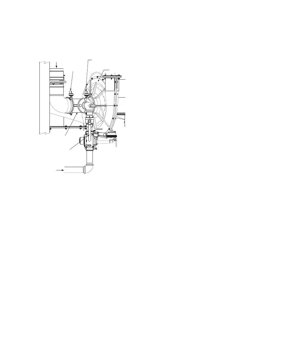
3. Close the manual gas shutoff valve located
between the Safety Shut-Off Valve (SSOV)
and the Air/Fuel Valve (see Figure 6-3).
MANUAL GAS
SHUTOFF VALVE
HANDLE
SSOV
AIR
INLET
AIR/FUEL
VALVE
BLOWER
GAS
INLET
PARTIAL LEFT SIDE VIEW
P/O FRAME
BLOCKED
INLET
SWITCH
BLOWER PROOF
SWITCH
Figure 6-3
Manual Gas Shut-Off Valve Location
4. Set the ON/OFF switch to the ON position to
start the unit.
5. The unit should shut down after reaching the
Ignition cycle and display FLAME LOSS
DURING IGN.
6. Open the valve previously closed in step 3
and press the CLEAR button.
7. Restart the unit and allow it to prove flame.
8. Once flame is proven, close the manual gas
valve located between the SSOV and the
Air/Fuel Valve.
9. The unit should shut down and display
FLAME LOSS DURING RUN.
10. Open the valve previously closed in step 8.
11. Press the CLEAR button. The unit should
restart and fire.
6.8 AIR FLOW FAULT TESTS
These tests check the operation of the Blower
Proof Switch and Blocked Inlet Switch shown in
Figure 6-3.
1. Disable the blower output drive voltage as
follows:
(a) Press the MENU key until CONFIGUR-
ATION MENU is displayed.
(b) 3UHVV WKH Ÿ DUURZ NH\ XQWLO WKH ANA-
LOG OUTPUT function is displayed,
then press the CHANGE key.
(c) 3UHVV WKH ź DUURZ NH\ XQWLO OFF is
displayed, then press the ENTER key.
2. Start the unit in the Manual Mode at a valve
position between 25% and 30%.
3. The unit should shut down and display
AIRFLOW FAULT DURING PURGE.
4. Re-enable the blower output drive voltage by
performing the following steps:
(a) Press the MENU key until CONFIGUR-
ATION MENU is displayed.
(b) 3UHVVWKHŸDUURZNH\XQWLOWKHANA-
LOG OUTPUT function is displayed,
then press the CHANGE key.
(c) 3UHVVWKHŸDUURZNH\XQWLOVALVE
POSITION 0-10V is displayed, then
press the ENTER key.
5. Once the unit has proved flame, turn off the
blower by going to the Configuration Menu,
Analog Output menu item and select OFF.
6. The Blower Proof Switch will open and the
blower should stop. The unit should shut
down and display AIRFLOW FAULT
DURING RUN.
7. Go to the Configuration Menu, Analog Output
item and select Valve Position 0-10v.
8. Press the CLEAR button. The unit should
restart.
9. Next, check the Blocked Inlet Switch by first
noting the current position of the Iris Air
Damper and then closing the Damper to
position 8.