Initial start-up – AERCO BMK 3.0 LN Natural Gas July 2011 User Manual
Page 37
INITIAL START-UP
4-3
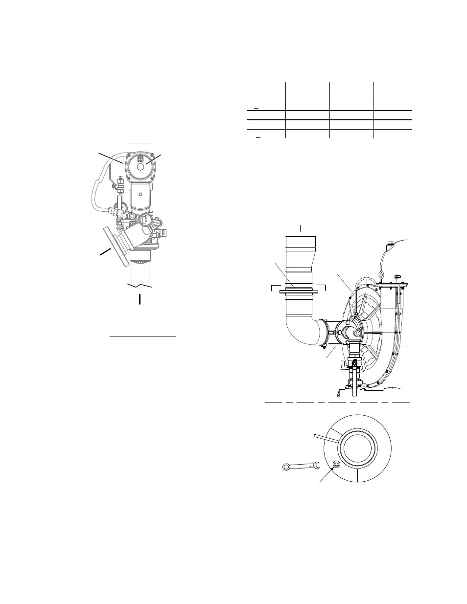
10. Next, verify that the gas pressure
downstream of the SSOV is 1.8” W.C. for
both FM and IRI gas trains. If gas pressure
adjustment is required, remove the brass
hex nut covering the SSOV gas pressure
adjustment screw (Figure 4-3). Make gas
pressure adjustments using a flat-tip
screwdriver to obtain 1.8” W.C.
SSOV
TO
AIR/FUEL
VALVE
GAS
INLET
BRASS HEX
HEAD CAP
(REMOVE TO
ACCESS GAS
PRESSURE
ADJUSTMENT
SCREW
FRONT
PARTIAL TOP VIEW
Figure 4-3
Regulator Adjustment Screw Location
11. Increase the valve open position to 100%
and verify that the gas pressure downstream
of the SSOV remains at 1.8” W.C. Readjust
pressure if necessary. -
12. With the valve position at 100%, insert the
combustion analyzer probe into the flue
probe opening and allow enough time for the
combustion analyzer to settle.
13. Compare the measured oxygen level to the
oxygen range for the inlet air temperature
shown in Table 4-1. Also, ensure that the
carbon monoxide (CO) and nitrogen oxide
(NOx) readings do not exceed the values
shown.
Table 4-1
Combustion Oxygen Levels for a 100%
Open Air/Fuel Valve Position
Inlet Air
Temp
Oxygen %
± 0.2
Carbon
Monoxide
NOx
>100°F
4.8 %
<100 ppm <30 ppm
90°F
5.0 %
<100 ppm <30 ppm
80°F
5.2 %
<100 ppm <30 ppm
<70°F
5.3 %
<100 ppm <30 ppm
14. If necessary, adjust the iris air damper
shown in Figure 4-4 until the oxygen level is
within the range specified in Table 4-1.
15. Once the oxygen level is within the specified
range at 100%, decrease the valve position
to 70%.
IRIS AIR
DAMPER
AIR INLET
BLOWER
AIR/FUEL
VALVE
A
A
USE 1 /2"
WRENCH TO
INCREASE (CW)
OR DECREASE
(CCW) INLET AIR
IRIS ADJUSTMENT
VIEW A - A
Figure 4-4
Iris Air Damper Location/Adjustment