Installation – AERCO BMK 3.0 LN Natural Gas July 2011 User Manual
Page 22
INSTALLATION
2-10
2.10.9 EXHAUST SWITCH IN
These terminals permit an external exhaust
switch to be connected to the exhaust manifold
of the boiler. The exhaust switch should be a
normally open type switch (such as AERCO Part
No. 123463) that closes (trips) at 500°F.
2.10.10 INTERLOCKS
The unit offers two interlock circuits for
interfacing with Energy Management Systems
and auxiliary equipment such as pumps or
louvers. These interlocks are called the Remote
Interlock and Delayed Interlock (Figure 2-11).
The wiring terminals for these interlocks are
located inside the I/O Box on the unit front
panel. The I/O Box cover contains a wiring
diagram which shows the terminal strip locations
for these interlocks (REMOTE INTL’K IN and
DELAYED INTL’K IN). Both interlocks,
described below, are factory wired in the closed
position.
IMPORTANT
Both the Remote Interlock and Delayed
Interlock MUST be in the closed position
to allow the unit to fire.
2.10.10.1 REMOTE INTERLOCK IN
The remote interlock circuit is provided to
remotely start (enable) and stop (disable) the
Boiler, if desired. The circuit is labeled
REMOTE INTL’K IN and is located inside the I/O
Box on the front panel. The circuit is 24 VAC
and is factory pre-wired in the closed (jumpered)
position.
2.10.10.2 DELAYED INTERLOCK IN
The delayed interlock is typically used in
conjunction with the auxiliary relay described in
paragraph 2.10. This interlock circuit is located
in the purge section of the start string. It can be
connected to the proving device (end switch,
flow switch etc.) of an auxiliary piece of
equipment started by the Boiler’s auxiliary relay.
The delayed interlock must be closed for the
boiler to fire.
If the delayed interlock is connected to a proving
device that requires time to close (make), a time
delay (Aux Start On Dly) that holds the start
sequence of the boiler long enough for a proving
switch to make can be programmed. Should the
proving switch not prove within the programmed
time frame, the boiler will shut down. The Aux
Start On Dly can be programmed from 0 to 120
seconds. This option is locate in the
Configuration Menu (Chapter 3, Table 3-4).
2.10.11 FAULT RELAY
The fault relay is a single pole double throw
(SPDT) relay having a normally open and
normally closed set of relay contacts that are
rated for 5 amps at 120 VAC and 5 amps at 30
VDC. The relay energizes when any fault
condition occurs and remains energized until the
fault is cleared and the CLEAR button is
depressed. The fault relay connections are
shown in Figure 2-11.
2.10.12
BENCHMARK PUMP RELAY
OPTION
An optional Benchmark pump relay allows the
user to turn a pump on/off and open/close a
motorized valve as the boiler cycles on and off
on demand. The Pump Delay Timer feature
allows the user to keep the pump running and
keep the motorized valve open for up to 30
minutes after the boiler has shut down and the
demand is satisfied.
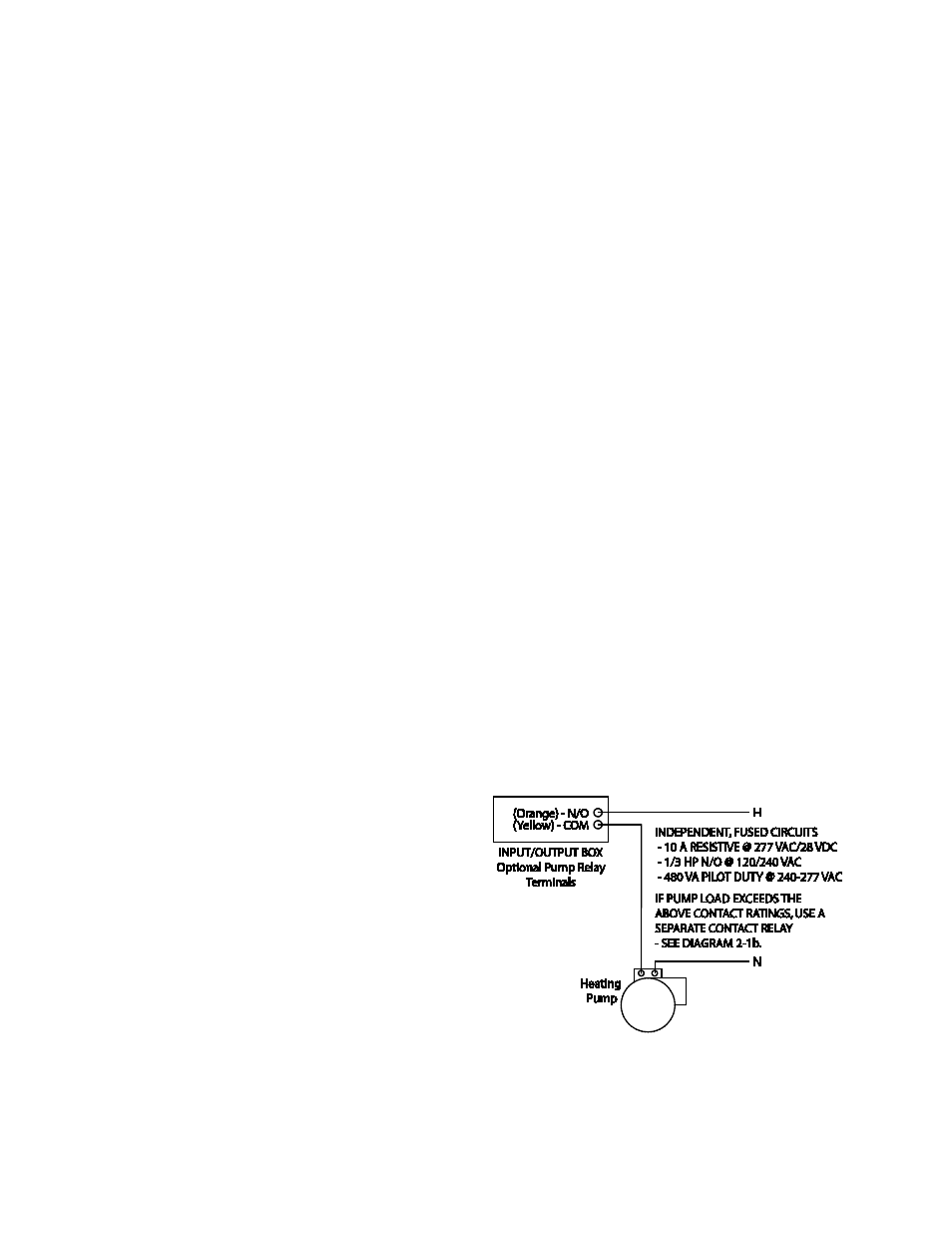
The Benchmark pump relay (SPDT) contact is
rated for:
•
10 A Resistive @ 277 VAC/28 VDC
•
1/3 HP N/O @ 120/240 VAC
•
1/6 HP N/C @ 120/240 VAC
•
480 VA Pilot Duty @ 240-277 VAC
If pump/valve load exceeds the above contact
ratings, use a separate contact relay.
See Diagrams 2-1a and 2-1b.
To identify if the boiler is equipped with the BMK
Pump Relay Option (part no. 69102), look for the
label and relay as shown in Figure 2-12.
Diagram 2-1a: Schematic – System Pump
Start using Boiler Pump Relay