Circuit diagram, Dimensions, Sensor head – KEYENCE IG Series User Manual
Page 9: Sensor amplifier, Z output circuit, Z analog output circuit z input circuit, Z ig-010
9
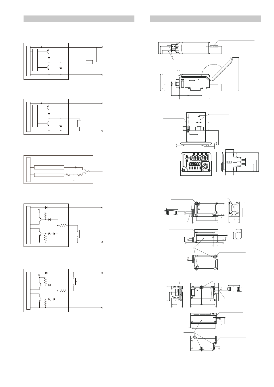
Circuit Diagram
Sensor head
z Output circuit
When NPN output is selected
When PNP output is selected
z Analog output circuit
z Input circuit
When NPN output is selected
When PNP output is selected
Dimensions
Sensor amplifier
z IG-1000/IG-1050
z IG-1500/IG-1550
Sensor head
z IG-010
Transmitter
Receiver
M
ain cir
cuit
Ov
er
curr
ent pr
ot
ec
tion cir
cuit
10 to 30 VDC
Brown
0 V
Blue
*
Load
* Black (HIGH output)/White (LOW output)/
Gray (GO output)/Green (edge check output)
10 to 30 VDC
0 V
* Black (HIGH output)/White (LOW output)/
Gray (GO output)/Green (edge check output)
Main cir
cuit
Over
curr
ent pr
otection cir
cuit
Brown
Blue
*
Load
Main cir
cuit
Analog current output circuit
Analog voltage output circuit
(Switching number)
Shield
Orange
Analog output GND
Analog voltage/
current output
0 to 5 V, 1 to 5 V,
-5 to 5 V, 4 to 20 mA
10 to 30 VDC
0 V
*
Brown
Blue
Main cir
cuit
* Pink (External input 1)/Yellow (External input 2)/
Pink·Purple(External input 3)/
Purple (External input 4)
(Short-circuit current 2 mA or less)
+5V
10 to 30 VDC
0 V
*
* Pink (External input 1)/Yellow (External input 2)/
Pink·Purple(External input 3)/
Purple (External input 4)
(Short-circuit current 2 mA or less)
Brown
Blue
Main cir
cuit
Cable diameter
φ4.8
Cable diameter
φ4.7 Cable length 2 m
28.3
42.4
37.4
17.4
18.5
18.5
8.9
20 21.6
35.4
76.3
17.6
When the cover is open: Max. 109.2
Max. 135°
3
44.7
15.3
4
9.5
1.5
35
20.2
2.3
7.6
73.6
48
19.1
19.1
10.3
10.3
17.6
27.2
44.7
Cable diameter
φ4.8
Cable diameter
φ4.7
Cable length 2 m
* Transmission spot
(reference
value)
Transmission spot center
φ4.8 Cable length 170
Edge M8 connector
12
15
17
(26)
φ9
39.8
54.7
6.7
3.2
25.4
23
11.2
18.8
31.8
3-M3 Valid screw depth 4
50.5
32.7
10.6
4.8
6.7
3.7
10.4
1.6
Base
level
2-M4
Valid screw depth
5.2
2-
φ3.4 (Mounting hole)
* Light-receiving area
(5x14
rectangle)
Measurement center
31.8
18.8±1
11.2
23
51.5
12.6
23.5
28.5
55
16.2
φ4.8 Cable length 170
Edge M8 connector
3-M3 Valid screw depth 4
2-M4 Valid screw depth 5.2
3
49.4
4.3
13.5
Base level
2-
φ3.4 (Mounting hole)
(26)
φ9