Optical axis alignment, Setting the tolerance setting value (threshold), Automatic setting (tolerance tuning) – KEYENCE IG Series User Manual
Page 6: Automatic setting (2-point tuning), Z sub display, Reference
6
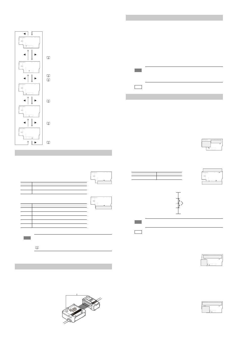
z Sub display
The sub display switches each time the
W/X button is pressed. According to the type of
displayed value selected, the sub display identification indicator will show one of the
following: [R.V. / ANALOG / HI / LO / SHIFT]
Operation When the Power is Turned on for the First Time
When the amplifier is turned on for the first time after the sensor head is connected, the initial setting
display appears. Make the initial setting according to the following procedure as this is necessary for
both the main unit and the expansion units when units are added.
1
Press the
S/T button to select the polarity of the signal
output and the edge check output and press the [MODE]
button.
2
Press the
S/T button to select the analog output method and
press the [MODE] button.
After the setting is complete, [
GPF] blinks several times on the sub display and changes to the basic display.
3
Perform “Optical Axis Alignment” and “Standard Light-Receiving Amount Registry” (page 6).
Make other settings as necessary.
Optical Axis Alignment
If the optical axis alignment indicators [ALIGNMENT] of transmitter, receiver and amplifier do not both
light up upon power up, align the optical axis of the sensor head.
Adjust the angle of the transmitter and receiver while a target object is not present within
the measuring range. Then fix mount the transmitter and receiver once the alignment
indicators [ALIGNMENT] light up.
Registering the standard waveform (Gain adjustment)
The measurments will be stabilized once the standard waveform has been registered. (Gain adjustment)
The total light received will be registered as 100%.
Register the standard waveform when the unit is used for the first time, when the setting
environment is changed, or when the measurement sensitivity is changed. For details, refer to
the User’s Manual.
1
Confirm that the optical axis alignment indicators [ALIGNMENT] of the transmitter,
receiver and amplifier are lit up.
If the optical axis adjustment indicators are off, align the optical axis.
2
Press the [MODE] and [SET] buttons at the same time for approx. 2 seconds on the
basic display.
[
CNKIP] is displayed on the main display (upper level) and the standard waveform will
be registered. The basic display will be restored when the registry is complete.
Setting the Tolerance Setting Value (Threshold)
There are two types of tolerance setting values: HIGH (upper limit) and LOW (lower limit) The
value displayed will output its signal as one of the following 3 levels: When the value exceeds the
upper limit (HIGH); when the value is within the tolerance range (GO); and when the value falls
below the lower limit (LOW)
"4. Output format" (page 8)
Automatic setting (Tolerance tuning)
When the object to be measured is present, and the measurement value for the master
workpiece is set, the HIGH (upper limit) and LOW (lower limit) will be automatically set with
the master workpiece measurement value centered.
1
Press the
W/X buttons several times on the basic display.
Then display the R.V. (internal measurement value) on the
sub display (lower level).
2
Measure the master workpiece and press the [SET] button.
The P.V. (judgment value) will be set as a standard value for
the tolerance settings.
[
UGV] and the tolerance setting width are displayed alternately on the sub display
(lower level).
3
Press the
S/T buttons to set the tolerance width and press the [SET] button.
After [
UGV] blinks several times, the display returns to the R.V.
(internal measurement value).
The tolerance tuning is complete.
Automatic setting (2-point tuning)
The following will explain how to set up a mean tolerance level that distinguishes between
acceptable vs. defective targets.
1
Press the
W/X buttons several times until the HIGH tolerance
value on the sub display (lower level) is shown.
2
Place the acceptable target within the measuring range and
press the [SET] button.
The R.V. (internal measurement value) will be registered and
[
JKUGV] will be shown on the main display (upper level).
3
Now place the defective target within the measuring range and press the [SET] button.
The R.V. (internal measurement value) will be registered and after [
UGV] blinks on the
main display (upper level), the P.V. (judgment value) will be shown.
On the sub display (lower level), the medium value between the acceptable target
value registered in step 2 and the HIGH side defective target value will now be
displayed.
The HIGH tolerance value (upper limit) is now setup.
4
Press the
X button once and display the LOW tolerance value
on the sub display (lower level).
5
Measure the acceptable target again and press the [SET]
button.
The R.V. (internal measurement value) is now registered.
[
NQUGV] will be shown and on the main display (upper level).
R.V. (internal measurement value)
The actual measurement value for the object is displayed.
This displayed value is not held.
• With the pin size judging mode or pin interval judging mode,
the R.V. (internal measurement value) for each pin size and
each pin interval can be displayed.
“1. Measurement mode” (page 8)
The analog output will only be displayed for the main unit and
only when it is enabled.
The voltage value (unit: V) or current value (unit: mA) of the
analog output is displayed.
“Operation When the Power is Turned on for the First Time” (page 6)
“Initial Reset (Initialize)” (page 7)
HIGH side setting value
The upper limit of the acceptable range (tolerance setting value) for
the object that is being measured is displayed. Also, the setting
value can be changed. If the P.V. (judgment value) exceeds the
value set here, the HIGH output signal will be sent.
“Setting the Tolerance Setting Value” (page 6)
LOW side setting value
The lower limit of the acceptable range (tolerance setting value)
for the object that is being measured is displayed. Also, the
setting value can be changed. If the P.V. (judgment value) falls
below the value set here, the LOW output signal will be sent.
“Setting the Tolerance Setting Value” (page 6)
Shift target value
When the zero shift button is pressed or the zero shift input is
set to ON, the R.V. (internal measurement value) will be
matched to the value set here.
“Zero shift function” (page 7)
Setting value
Description
PRP
NPN output
RPR
PNP output
Setting value
Description
QHH
Not output
W
Analog output after the judgment value is converted to the range from 0 to 5 V.
W
Analog output after the judgment value is converted to the range of ±5 V.
W
Analog output after the judgment value is converted to the range from 1 to 5 V.
CORT
Analog output after the judgment value is converted to the range from 4 to 20 mA.
Note
The initial setting display appears only when the power is turned on for the
first time. It will not appear when the power is turned on the second time or
thereafter. To change the initial setting, perform the initial reset.
“Initial Reset (Initialize) page 7”
LASER
BANK
0
1
2
3
HI
LO
R.V.
ANALOG
HI
SHIFT
ZERO SHIFT
TIMING
LO
ALIGNMENT
HOLD
CALC
CHECK
GO
GO
HOLD
CALC
CHECK
X
LASER
BANK
0
1
2
3
HI
LO
R.V.
ANALOG
HI
SHIFT
ZERO SHIFT
TIMING
LO
ALIGNMENT
GO
LASER
BANK
0
1
2
3
HI
LO
R.V.
ANALOG
HI
SHIFT
ZERO SHIFT
TIMING
LO
ALIGNMENT
HOLD
CALC
CHECK
GO
HOLD
CALC
CHECK
LASER
BANK
0
1
2
3
HI
LO
R.V.
ANALOG
HI
SHIFT
ZERO SHIFT
TIMING
LO
ALIGNMENT
GO
HOLD
CALC
CHECK
LASER
BANK
0
1
2
3
HI
LO
R.V.
ANALOG
HI
SHIFT
ZERO SHIFT
TIMING
LO
ALIGNMENT
PRP
LASER
BANK
0
1
2
3
HI
LO
R.V.
ANALOG
HI
SHIFT
ZERO SHIFT
TIMING
LO
ALIGNMENT
QWV
GO
HOLD
CALC
CHECK
Output polarity
QHH
LASER
BANK
0
1
2
3
HI
LO
R.V.
ANALOG
HI
SHIFT
ZERO SHIFT
TIMING
LO
ALIGNMENT
#P.)
GO
HOLD
CALC
CHECK
Analog output
Transmitter
Receiver
Optical axis alignment indicator [ALIGNMENT]
Note
If attempting to register the standard waveform while the optical axis
alignment indicators [ALIGNMENT] are off, an error message will be
displayed and the standard waveform cannot be registered.
“Error message and countermeasures” (page 8)
Reference
The standard waveform can be registered by the external input as well.
Select the "Gain input" for the external input 4 (purple wire).
Setting range
Default value
0.000 to 99.999
0.100
Note
The tolerance tuning cannot be performed when the P.V. (judgment
value) is displayed as [
].
Reference
When the tuning result exceeds the setting range (-99.999 to 99.999), the
limit values of the setting range become the High and Low tolerances.
LASER
BANK
0
1
2
3
HI
LO
R.V.
ANALOG
HI
SHIFT
ZERO SHIFT
TIMING
LO
ALIGNMENT
HOLD
CALC
CHECK
GO
R.V. value
[R.V.]
lights up.
GO
HOLD
CALC
CHECK
LASER
BANK
0
1
2
3
HI
LO
R.V.
ANALOG
HI
SHIFT
ZERO SHIFT
TIMING
LO
ALIGNMENT
Tolerance setting width
Master work P.V.
Tolerance tuning setting width
Measurement upper limit value
Measurement lower limit value
LOW tolerance value (lower limit)
Master workpiece P.V. (judgment value)
HIGH tolerance value (upper limit)
GO
LASER
BANK
0
1
2
3
HI
LO
R.V.
ANALOG
HI
SHIFT
ZERO SHIFT
TIMING
LO
ALIGNMENT
HOLD
CALC
CHECK
[HI]
lights up.
HIGH tolerance value
GO
HOLD
CALC
CHECK
LASER
BANK
0
1
2
3
HI
LO
R.V.
ANALOG
HI
SHIFT
ZERO SHIFT
TIMING
LO
ALIGNMENT
LOW tolerance value
[LO]
lights up.