Zero shift function, Initial reset (initialize), Setting method – KEYENCE IG Series User Manual
Page 7: T'5'v, Manual setting, Setting the shift target value, Activating the zero shift, Cancelling the zero shift, Basic operations on the setting display, Setting procedures (basic)
7
6
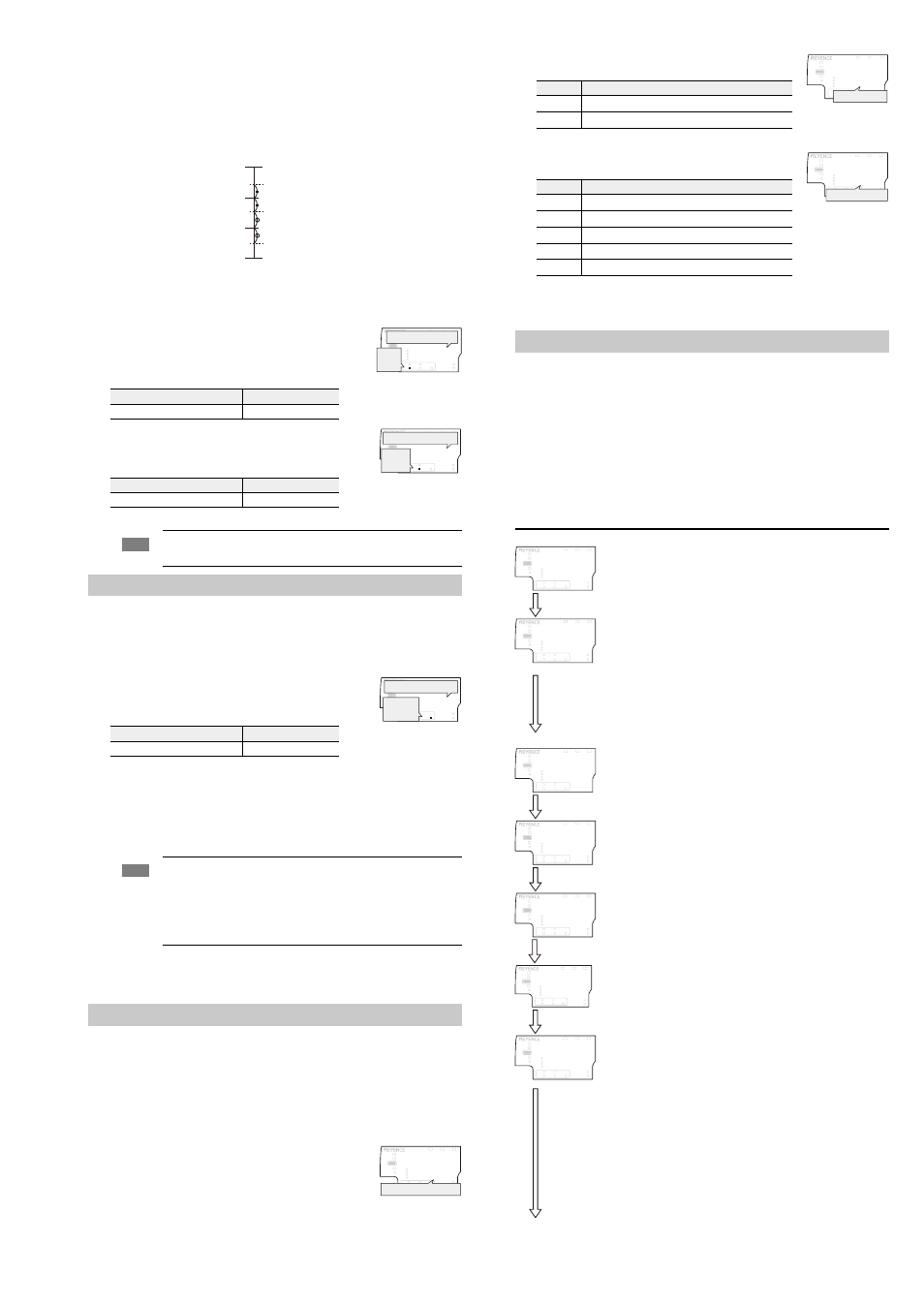
Measure the LOW side defective target and press the [SET] button.
The R.V. (internal measurement value) is now registered.
After [
UGV] blinks on the main display (upper level), the P.V. (judgment value) will be
shown.
On the sub display (lower level), the medium value between the acceptable target
value registered on step 5 and the LOW side defective target value will be displayed.
The LOW side setting value (lower limit) is complete.
The 2-point tuning is complete.
Manual setting
Set the HIGH tolerance value (upper limit) and LOW tolerance value (lower limit) to an
arbitrary value.
1
Press the
W/X buttons several times on the basic display.
Then display the HIGH side setting value on the sub display
(lower level).
2
Press
S/T buttons to set the HIGH tolerance value.
3
Press the
X button once and display the LOW tolerance value
on the sub display (lower level).
4
Press the
S/T buttons to set the LOW side setting value.
The tolerance settings are complete.
Zero Shift Function
When the [ZERO SHIFT] button is pressed or the external zero shift input (pink wire) has
been activated, the R.V. (internal measurement value) now becomes the newly shifted
target value.
Setting the shift target value
1
Use the
W/X buttons on the basic display to navigate your
way to the shift target value on the sub display (lower level).
2
Press the
S/T buttons to change the shift target value.
The shift target value has now been set.
Activating the zero shift
Press the [ZERO SHIFT] button or short the external pink wire to 0V or 24VDC (based on
the NPN or PNP setup).
The zero shift indicator [ZERO SHIFT] will light up for approx. 0.5 second and the current
R.V. (internal measurement value) will now become the shifted target value.
Cancelling the zero shift
Press the zero shift button [ZERO SHIFT] for 2 seconds or more.
[
TGUGV] is displayed on the sub display and the zero shift is cancelled.
Initial Reset (Initialize)
The initial reset initializes all settings except for the calibration setting and standard
waveform registry (Gain adjustment).
When using initial reset, the output polarity (NPN / PNP) edge check output, and the analog
output settings can be changed.
1
While holding down the [MODE] button on the basic display, press the [SET] button 5
times.
[
TGUGV] will be displayed on the main display.
2
Press
S/T button to select [[GU] and press the [MODE]
button.
When [MODE] and [ZERO SHIFT] buttons are pressed at the
same time for approx. 2 seconds, the display units (inch / mm)
can be accessed. [
OO] and [KPEJ], represent “mm” and "inch"
respectively.
Press the [MODE] button.
3
Press
S/T button to select the output polarity and press the
[MODE] button.
4
Press the
S/T buttons to select the analog output and press
[MODE] button.
After the initialization is complete, [
GPF] blinks several times on the sub display and the
basic display is restored.
Setting Method
z Calling the setting display
Hold the [MODE] button for approx. 2 seconds on the basic display.
The setting display appears.
Basic operations on the setting display
To change the setting, press the
S/T button
To move the next item, press the [MODE] button or
X button
To return to the previous item, press the
W button
To skip the rest of the settings and finish: Press and hold the [MODE] button for approx. 2
seconds.
Setting procedures (Basic)
Setting range
Default value
-99.999 to 99.999
8.000
Setting range
Default value
-99.999 to 99.999
2.000
Note
When setting the tolerance value manually or with the 2-point tuning,
make sure to set “HIGH tolerance value then the LOW tolerance value”
Setting range
Default value
-99.999 to 99.999
0.000
Note
• When using the external zero shift function, any newly shifted states
will be lost when the unit is powered down unless the memory
function is utilized.
For details, refer to the User's Manual.
• When the R.V. (internal measurement value) is [
], the zero shift
function cannot be used.
Setting value for the HIGH side defective target
Setting value for the LOW side defective target
Setting value for the acceptable target
Measurement upper limit value
Measurement lower limit value
LOW tolerance value (lower limit)
HIGH tolerance value (upper limit)
GO
LASER
BANK
0
1
2
3
HI
LO
R.V.
ANALOG
HI
SHIFT
ZERO SHIFT
TIMING
LO
ALIGNMENT
HOLD
CALC
CHECK
[HI]
lights up.
HIGH tolerance value
GO
HOLD
CALC
CHECK
LASER
BANK
0
1
2
3
HI
LO
R.V.
ANALOG
HI
SHIFT
ZERO SHIFT
TIMING
LO
ALIGNMENT
LOW tolerance value
[LO]
lights up.
GO
HOLD
CALC
CHECK
LASER
BANK
0
1
2
3
HI
LO
R.V.
ANALOG
HI
SHIFT
ZERO SHIFT
TIMING
LO
ALIGNMENT
Shift target value
[SHIFT]
lights up.
;GU
LASER
BANK
0
1
2
3
HI
LO
R.V.
ANALOG
HI
SHIFT
ZERO SHIFT
TIMING
LO
ALIGNMENT
T'5'V
GO
HOLD
CALC
CHECK
Performing the initial reset
Setting value
Description
PRP
NPN output
RPR
PNP output
Setting value
Description
QHH
Not using the analog output
W
Analog output range is from 0 to 5 V.
W
Analog output range is from ±5 V.
W
Analog output range is from 1 to 5 V.
CORT
Analog output range is from 4 to 20 mA.
Basic display
Press the [MODE] button for 2 seconds.
“1. Measurement mode” Use
S/T to select.
Setting the edge control/positioning, outer
diameter/width, inner diameter/opening,
glass edge,
pin position (See User's Manual),
pin interval (See User's Manual),
pin diameter (See User's Manual),
specified edges interval (See User's
Manual)
Press the [MODE] or
X button.
“2. Measurement direction” Use
S/T to select.
Setting the top and bottom
Press the [MODE] or
X button.
“3. Averaging”
Use
S/T to select.
Setting the averaging
Press the [MODE] or
X button.
“4. Output state”
Use
S/T to select.
Setting N.O. (Normally Open) and N.C.
(Normally Closed)
Press the [MODE] or
X button.
“Basic setting complete” Press the [MODE] button or the
X button
to return to the basic display.
Press the
T or S button.
“Advanced settings”
See User’s Manual
Press the
W button to return to the basic
display.
When the advanced setting is selected, the
following items can be set. For details, see
the User’s Manual.
“5. Hold function” “6. Timing input” “7.
Delay timer” “8. Hysteresis” “9. Edge check
function” “10. Analog output scaling” “11.
External input” “12. Standard waveform
memory function” “13. Zero shift value
memory function” “14. Interference preven-
tion function” “15. Number of digit dis-
played” “16. Power saving function” “17.
Position monitor” “18. Display color”
Press the [MODE] or
X button.
Advanced setting
PRP
LASER
BANK
0
1
2
3
HI
LO
R.V.
ANALOG
HI
SHIFT
ZERO SHIFT
TIMING
LO
ALIGNMENT
QWV
GO
HOLD
CALC
CHECK
Output polarity
QHH
LASER
BANK
0
1
2
3
HI
LO
R.V.
ANALOG
HI
SHIFT
ZERO SHIFT
TIMING
LO
ALIGNMENT
#P.)
GO
HOLD
CALC
CHECK
Analog output
LASER
BANK
0
1
2
3
HI
GO
LO
R.V.
ANALOG
HI
SHIFT
ZERO SHIFT
TIMING
LO
ALIGNMENT
HOLD
CALC
CHECK
# '&)
LASER
BANK
0
1
2
3
HI
LO
R.V.
ANALOG
HI
SHIFT
ZERO SHIFT
TIMING
LO
ALIGNMENT
(PE
GO
HOLD
CALC
CHECK
VQR
LASER
BANK
0
1
2
3
HI
LO
R.V.
ANALOG
HI
SHIFT
ZERO SHIFT
TIMING
LO
ALIGNMENT
FKT
GO
HOLD
CALC
CHECK
LASER
BANK
0
1
2
3
HI
LO
R.V.
ANALOG
HI
SHIFT
ZERO SHIFT
TIMING
LO
ALIGNMENT
#W'
GO
HOLD
CALC
CHECK
PQ
LASER
BANK
0
1
2
3
HI
LO
R.V.
ANALOG
HI
SHIFT
ZERO SHIFT
TIMING
LO
ALIGNMENT
QWV
GO
HOLD
CALC
CHECK
'PF
LASER
BANK
0
1
2
3
HI
LO
R.V.
ANALOG
HI
SHIFT
ZERO SHIFT
TIMING
LO
ALIGNMENT
GO
HOLD
CALC
CHECK
LASER
BANK
0
1
2
3
HI
LO
R.V.
ANALOG
HI
SHIFT
ZERO SHIFT
TIMING
LO
ALIGNMENT
2TQ
GO
HOLD
CALC
CHECK