Error displays and corrective actions, Teq, T#p)g – KEYENCE IG Series User Manual
Page 8: Ttq, Ttf, Tt5, Basic functions 1. measurement mode, Measurement direction, Averaging (response time), Output method
8
Basic functions
1. Measurement mode
Setting the position to measure.
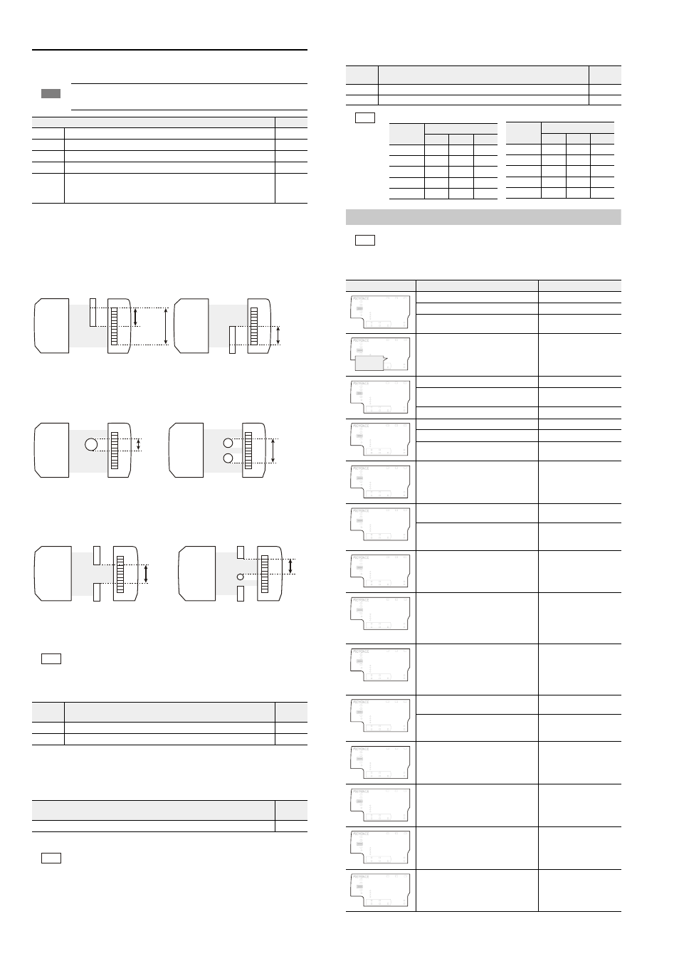
z Edge control/Positioning mode
When the measurement direction [
VQR] (top) is selected, the distance from the top edge of the
measurement range to bottom side of the measured target is the R.V. (internal measurement
value). When [
DVO] (bottom) is selected, the distance from the bottom edge of the measurement
range to the top side of the measured target is the R.V. (internal measurement value).
If there is no measurement target, R.V. (internal measurement value) will display [
].
z Outer diameter/Width measurement mode
The distance from the top edge of the target closest to the top of the measuring range to the
bottom edge of the target closest to the bottom of the measuring range will be calculated as
the R.V. (internal measurement value). If there is no target present, the R.V. (internal
measurement value) will display [
].
z Inner diameter/Opening measurement mode
The distance from the bottom edge of the target closest to the top of the measuring range to
the top edge of the next target near the bottom of the measuring range will be calculated as
the R.V. (internal measurement value).
If there is no target present, the R.V. (internal measurement value) will display [
].
z Glass edge mode
This operation is the same as that for the Edge control/Positioning mode, however the
measurement sensitivity is increased.
2. Measurement direction
Setting the measurement direction of the master workpiece to the sensor head.
3. Averaging (Response time)
The response time is the time from when the sensor head starts the measuring operation to the point where
the output signal is sent. When the average number of times is increased, the response time becomes
longer, but the R.V. (internal measurement value) and P.V. (judgment value) will be more stable.
4. Output method
Setting the judgment output method
Error Displays and Corrective Actions
Note
At the point when the selection is switched on the setting display, it is
reflected to the R.V. (internal measurement value).
Measurement mode
Default value
C.GFI
Edge control/Positioning mode,
c
D.FKC
Outer diameter/Width measurement mode
E.KPU
Inner diameter/Opening measurement mode
F.INU
Glass edge mode
G.RQU
to
J.WUT
Pin position measurement mode, Pin interval judgment mode,
Pin diameter judgment mode, Specified edge interval measurement
mode
Reference
For details of other measurement modes, see the User’s Manual.
Setting
value
Description
Default
value
VQR
Measures the distance from the top side of sensor head to the specified edge.
c
DVO
Measures the distance from the bottom side of sensor head to the specified edge.
Setting range
Default
value
JUR / / / / / / / / / / / /
Reference
• The response time for [
JR] (High speed) is 1.96 ms.
• 1 indicated in [
] means the average number. The response time can be calculated
256 times or less: Response time = Number of times for averaging x 0.98 + 2.94 ms
512 times or more: Response time = Number of times for averaging ÷ 256 x 257 x 0.98 + 1.96 ms
• When “Pin interval judgment mode” or “Pin diameter judgment mode” is
selected in “1. Measurement mode”, the setting range and the response
time will differ.
Measurement
range
R.V.
Top
Bottom
Top
Bottom
R.V.
Top
Bottom
Top
Bottom
When the measurement direction is [6Q2] When the measurement direction is [$6/]
R.V.
R.V.
Top
Bottom
Top
Bottom
Top
Bottom
Top
Bottom
R.V.
R.V.
Top
Bottom
Top
Bottom
Top
Bottom
Top
Bottom
Setting
value
Description
Default
value
PQ
Output is normally open
c
PE
Output is normally closed
Reference
Reference
"4. Output format" (page 8)
• The edge check output operates regardless of the error.
• When [
GTE] is displayed, all the outputs will turn OFF.
• When an error is displayed, the analog voltage output will be 5.5 V and
analog current output will be 3.0 mA.
Error indication
Error
Actions
The transmitter and receiver are not connected.
Connect the transmitter and receiver.
The transmitter and receiver are broken. Replace the transmitter and receiver.
The sensor head cable of the transmitter
and receiver is disconnected.
Replace the sensor head
cable.
The transmitter and receiver are
reversely connected to the amplifier.
Connect the transmitter
and receiver correctly.
The receiver is not connected.
Connect the receiver.
The receiver is broken.
Replace the transmitter
and receiver.
The sensor head cable of the receiver is disconnected
Replace the sensor head cable.
The transmitter is not connected.
Connect the transmitter.
The transmitter is broken.
Replace the transmitter and receiver.
The sensor head cable of the
transmitter is disconnected.
Replace the sensor head
cable.
The laser of the transmitter has been
damaged.
Replace the transmitter and
receiver.
Reading/writing the nonvolatile memory
(EEPROM) storage data failed.
Turn the power on again.
Data has been written in the nonvolatile
memory (EEPROM) over 500 thousands
times and malfunction occurred.
Replace the transmitter
and receiver.
The transmitter and receiver type
(Measurement range) do not match.
Replace with the same type
(measurement range) of the
transmitter and receiver.
The standard waveform was not
registered properly.
Do not turn off the sensor head
or disconnect it from the sensor
amplifier while registering the
standard waveform.
Register the standard waveform
again.
Overcurrent was detected on the
output.
• Check the load and
reduce the current to
within the rated range.
• Check that the output
wire does not touch
another wire or a frame.
Reading/writing the nonvolatile memory
(EEPROM) storage data failed.
Turn the power on again and
perform the initial reset.
Data has been written in the nonvolatile
memory (EEPROM) over 1 million times
and malfunction occurred.
Replace the amplifier unit if
data writing is necessary.
Communication is not possible
between the amplifiers.
Turn the power on and check
the connection status
between amplifiers.
The light-receiving amount is too large
to register the standard waveform.
Check whether too much
ambient light or light from
another sensor enters the
receiver or not.
The light-receiving amount is too small
to register the standard waveform.
• Align the optical axis so
the optical axis alignment
indicator lights up.
• Clean the sensor head's
transmitter and receiver.
The standard waveform cannot be
registered because the receiver is
receiving the laser light of the
transmitter from another amplifier.
Use the transmitter and
receiver associated with
their designated amplifier.
Normally open [
PQ]
judgment
judgment output
HIGH
GO
LOW
HIGH
ON
OFF
OFF
GO
OFF
ON
OFF
LOW
OFF
OFF
ON
[
]
OFF
OFF
OFF
Error
ON
OFF
ON
Normally closed [
PE]
judgment
judgment output
HIGH
GO
LOW
HIGH
OFF
ON
ON
GO
ON
OFF
ON
LOW
ON
ON
OFF
[
]
ON
ON
ON
Error
OFF
ON
OFF
V T
LASER
BANK
0
1
2
3
HI
LO
R.V.
ANALOG
HI
SHIFT
ZERO SHIFT
TIMING
LO
ALIGNMENT
'T*
GO
HOLD
CALC
CHECK
T V
LASER
BANK
0
1
2
3
HI
LO
R.V.
ANALOG
HI
SHIFT
ZERO SHIFT
TIMING
LO
ALIGNMENT
'T*
GO
HOLD
CALC
CHECK
Displayed
alternately.
T
LASER
BANK
0
1
2
3
HI
LO
R.V.
ANALOG
HI
SHIFT
ZERO SHIFT
TIMING
LO
ALIGNMENT
'T*
GO
HOLD
CALC
CHECK
V
LASER
BANK
0
1
2
3
HI
LO
R.V.
ANALOG
HI
SHIFT
ZERO SHIFT
TIMING
LO
ALIGNMENT
'T*
GO
HOLD
CALC
CHECK
.#5'4
LASER
BANK
0
1
2
3
HI
LO
R.V.
ANALOG
HI
SHIFT
ZERO SHIFT
TIMING
LO
ALIGNMENT
'T*
GO
HOLD
CALC
CHECK
4''2
LASER
BANK
0
1
2
3
HI
LO
R.V.
ANALOG
HI
SHIFT
ZERO SHIFT
TIMING
LO
ALIGNMENT
'T*
GO
HOLD
CALC
CHECK
T#P)G
LASER
BANK
0
1
2
3
HI
LO
R.V.
ANALOG
HI
SHIFT
ZERO SHIFT
TIMING
LO
ALIGNMENT
'T*
GO
HOLD
CALC
CHECK
#.K)P
LASER
BANK
0
1
2
3
HI
LO
R.V.
ANALOG
HI
SHIFT
ZERO SHIFT
TIMING
LO
ALIGNMENT
'T*
GO
HOLD
CALC
CHECK
LASER
BANK
0
1
2
3
HI
LO
R.V.
ANALOG
HI
SHIFT
ZERO SHIFT
TIMING
LO
ALIGNMENT
'T%
GO
HOLD
CALC
CHECK
LASER
BANK
0
1
2
3
HI
LO
R.V.
ANALOG
HI
SHIFT
ZERO SHIFT
TIMING
LO
ALIGNMENT
'T'
GO
HOLD
CALC
CHECK
LASER
BANK
0
1
2
3
HI
LO
R.V.
ANALOG
HI
SHIFT
ZERO SHIFT
TIMING
LO
ALIGNMENT
'TEQ/
GO
HOLD
CALC
CHECK
'TTQ
LASER
BANK
0
1
2
3
HI
LO
R.V.
ANALOG
HI
SHIFT
ZERO SHIFT
TIMING
LO
ALIGNMENT
#.K)P
GO
HOLD
CALC
CHECK
'TTF
LASER
BANK
0
1
2
3
HI
LO
R.V.
ANALOG
HI
SHIFT
ZERO SHIFT
TIMING
LO
ALIGNMENT
#.K)P
GO
HOLD
CALC
CHECK
'TT5
LASER
BANK
0
1
2
3
HI
LO
R.V.
ANALOG
HI
SHIFT
ZERO SHIFT
TIMING
LO
ALIGNMENT
#.K)P
GO
HOLD
CALC
CHECK