Mounting the sensor head – KEYENCE IG Series User Manual
Page 3
3
DIN rail mount type, expansion unit (IG-1050)
Up to 3 expansion units can be connected to one main unit.
1
Remove the expansion protective cover from the IG-1000 (main unit).
2
Install the amplifiers (main and expansion units) onto the DIN rail.
3
Push the expansion unit into the main unit connector until a clicking sound can be heard.
4
Install the end units (OP-26751: 2 units per set) (sold separately) on both sides of the
amplifiers (main or expansion units). Secure the end units in place with screws on top
(2 on each end unit).
The end units are mounted in the same way as the amplifiers.
Panel mount type, main unit (IG-1500)
1
Make a hole on the panel to attach according to the measurement below.
2
Insert the back side of amplifier to the hole of the panel.
3
Arrange the panel mounting tool in the direction below, mount to the amplifier from the
back and attach the front protection cover to the amplifier.
To remove the panel mounting tool, widen the
claws at both ends of the panel mounting tool using
a slotted screwdriver, as demonstrated in the
pictorial on the right.
Panel mount type, expansion unit (IG-1550)
Up to 3 expansion units can be connected to one main unit.
1
Make the appropriate number of hole in the panel according to the number of
amplifiers required (main and connected expansion units).
For the panel cutting measurement, refer to the “Panel mount type, main unit”.
2
Install the amplifiers (expansion units) on the panel.
For the amplifier mounting method, refer to the “Panel mount type, main unit”.
3
Connect the amplifiers (main and expansion units) using the expansion cable (50 mm)
supplied with the expansion unit.
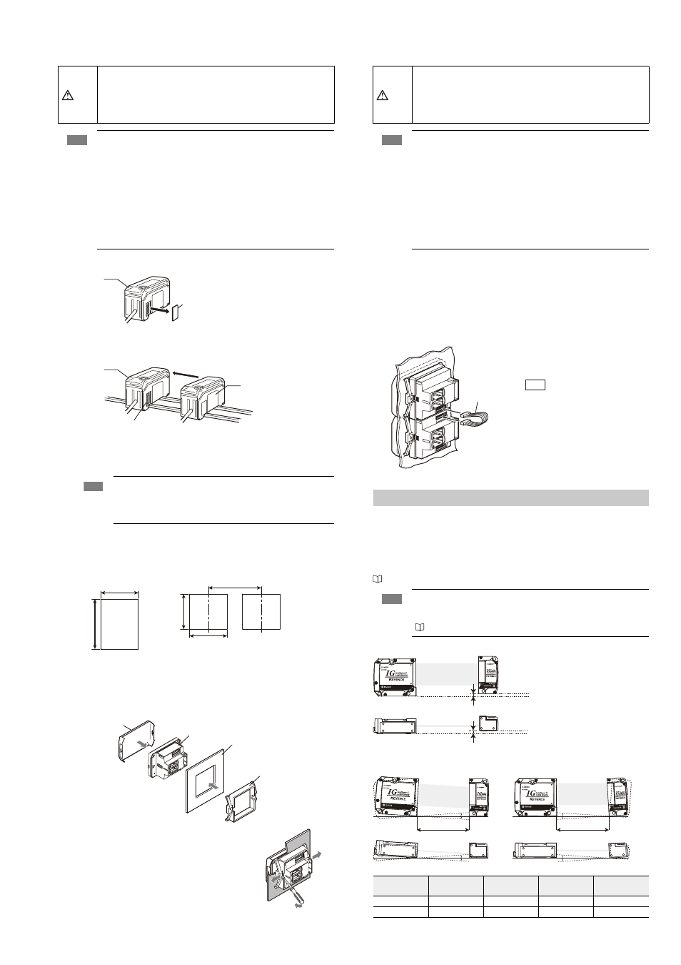
Mounting the Sensor Head
If the mounting distance between the transmitter and receiver is as follows, the optical axis
alignment is not required when mounting within the “parallel acceptable range” and “tilt
acceptable range”.
• IG-010 : 3 to 500 mm
• IG-028 : 50 to 500mm
However if the distance is out of the above range(s), adjust the optical axis after mounting.
“Optical axis alignment” (page 6)
z Parallel acceptable range
z Tilt acceptable range
Tilt of transmitter
Tilt of receiver
CAUTION
• When connecting multiple amplifiers (expansion units), first check to make sure
that the power is turned off to all of the main and expansion units. Connecting
the units with the power turned on could damage them.
• Push the amplifiers (expansion units) as far as possible into the main unit. If they
are connected at an angle or not inserted securely, the units could get damaged.
Note
• When connecting the expansion units, make sure to initialize the
expansion units and set the output polarity.
(1) When turning on the amplifier for the first time after connecting the sensor head
please reference
“Operation When the Power is Turned on for the First Time” (page 6)
(2) When initializing the unit please reference
“Initial Reset (Initialize)” (page 7)
• Expansion units with different setting of output polarity (such as an NPN output
expansion unit to a PNP output main unit) cannot be connected together.
• Expansion units using DIN rail mount cannot be connected to a panel
mount style main unit.
Note
Mount the amplifiers securely using the end units (OP-26751: 2 units
per set) (sold separately) or a commercially available DIN rail mounting
tool to prevent the amplifiers from slipping and coming off from the DIN
rail due to machine vibration.
Connector cover
Main unit
Connecter
Expansion unit
Main unit
· Thickness of the panel mounting part 1 to 6 mm
· X = 48 × (Number of amplifier) - 3
+ 0.6
- 0
45
mm
+ 0.6
- 0
45
mm
+ 0.6 - 0
45
mm
X mm
Minimum 85 mm
When arranging
lengthwise to attach
When arranging widthwise
to attach
Panel mounting tool
Panel
Sensor amplifier
Front protection cover
CAUTION
• When connecting the expansion cable, make sure to turn off the power
beforehand. Inserting or removing the cable with the power turned on may
cause damage to the units.
• Push the expansion cable connector securely all the way. If it is connected
at an angle or not inserted securely, the units could get damaged.
Note
• When connecting the expansion units, make sure to initialize the
connected expansion units and set the output polarity.
(1) When turning on the amplifier for the first time after connecting the sensor head
please reference
“Operation When the Power is Turned on for the First Time” (page 6)
(2) When initializing the unit please reference
“Initial Reset (Initialize)” (page 7)
• Expansion units with different setting of output polarity (such as an NPN output
expansion unit to a PNP output main unit) cannot be connected together.
• Expansion units using panel mount cannot be connected to a DIN rail
mounted main unit.
Reference
When arranging the
amplifiers as depicted in
the pictorial on the left, the
300 mm expansion cable
(OP-35361) is required.
Note
The minimum detectable object, linearity and temperature characteristics
found in the specifications are valid only if the sensor head is mounted within
the “parallel acceptable range” and “tilt acceptable range”.
“Specifications” (page 10)
Mounting
distance
A
B
C
D
500 mm or less
within ±0.05°
within ±0.05°
within ±1°
within ±2°
100 mm or less
within ±0.2°
within ±0.2°
within ±1°
within ±2°
Expansion
cable
Transmitter
Receiver
Transmitter
Receiver
within ± 0.5 mm
within ± 0.5 mm
Transmitter
Receiver
Transmitter
Receiver
Mounting distance
Transmitter
Receiver
Transmitter
Receiver
Mounting distance
A
C
D
B