Specifications, Warranty, Sensor amplifier – KEYENCE IG Series User Manual
Page 10: Sensor head, Z ig-028
10
Copyright (c) 2010 KEYENCE CORPORATION. All rights reserved.
11149E 1070-3 96M11149 Printed in Japan
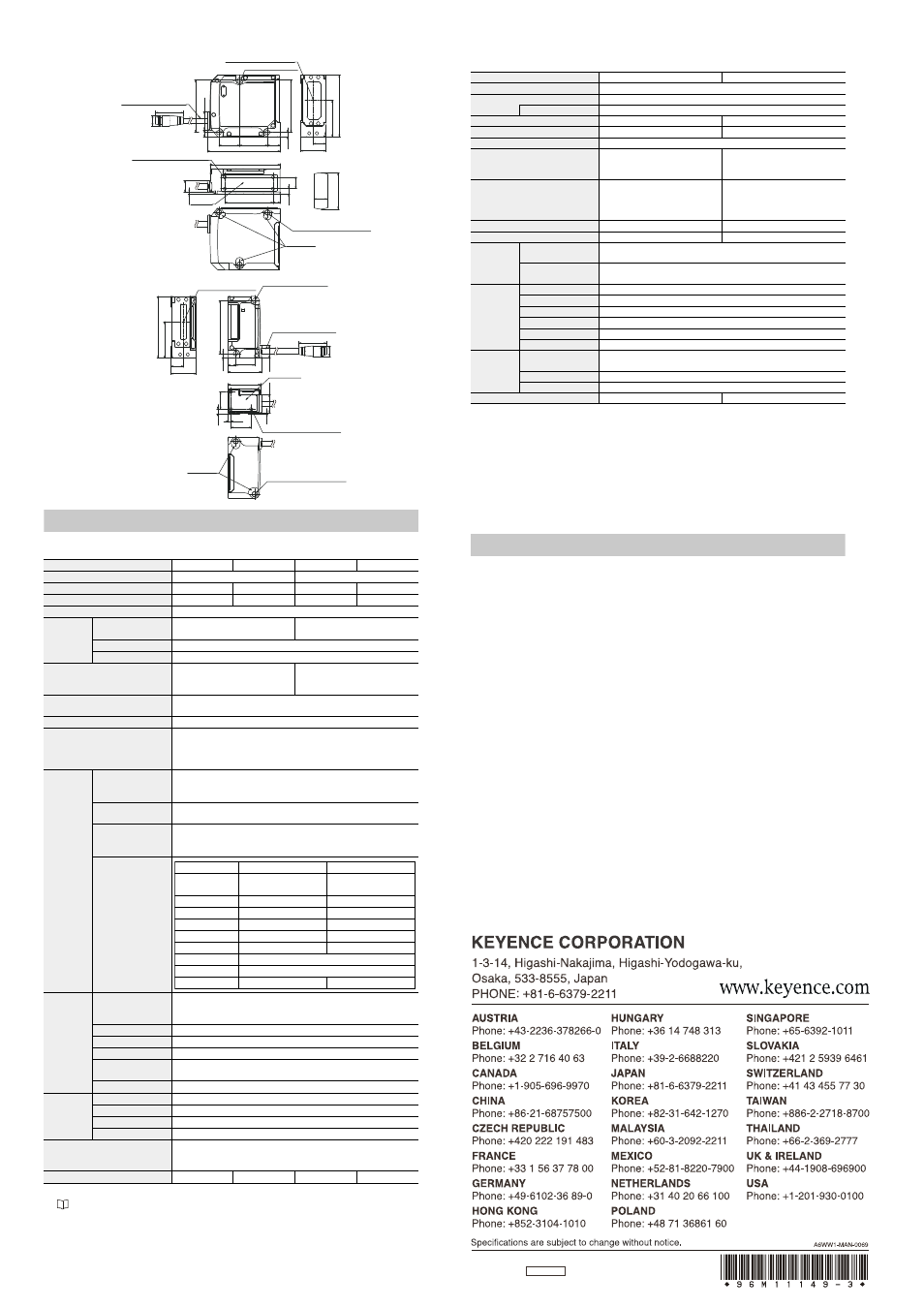
z IG-028
Transmitter
Receiver
Specifications
Sensor amplifier
*1 When expansion units are added: Max. 20 mA/ch
*2
“3. Average number of times” (page 8)
*3 Delay time that occurs from the analog output circuit after the judgment is output.
*4 For detailed time chart, refer to the User’s Manual.
Sensor head
*1 The classification is based on IEC60825-1 standard following the Laser Notice No.50 from FDA (CDRH).
*2 When the measurement target object is measured at the center position of the setting distance.
When the sensitivity setting is set to the high sensitivity mode:
I0.1mm (Setting distance: 100 mm)
When the measurement mode is set to the glass edge mode, a glass edge of C0.1 mm or more can be detected (Setting
distance: 500 mm).
*3 When the light quantity from the transmitter is cut by half at the center position of the setting
distance.
Vibration width when the averaging is set to 16 and sampling is performed for 30 seconds
(When the analog output is used, the margin of error of analog output is added.)
*4 When the setting distance is 100 mm, and light from the transmitter is blocked by an object at 50
mm from the receiver.
Margin of error to the ideal line.
*5 When the setting distance is 100 mm, and light is shielded by half at 50 mm position from the receiver.
*6 Excluding when the average number of times is set to [
JUR]
Warranty
KEYENCE products are strictly factory-inspected. However, in the event of a failure, contact
your nearest KEYENCE office with details of the failure.
1. WARRANTY PERIOD
The warranty period shall be for one year from the date that the product was delivered to the
location specified by the purchaser.
2. WARRANTY SCOPE
(1) If a failure attributable to KEYENCE occurs within the above mentioned warranty period, we will repair the
product, free of charge. However, the following cases shall be excluded from the warranty scope.
• Any failure resulting from improper conditions, improper environments, improper handling,
or improper usage other than described in the instruction manual, the user’s manual, or the
specifications specifically arranged between the purchaser and KEYENCE.
• Any failure resulting from factors other than a defect of our product, such as the
purchaser’s equipment or the design of the purchaser’s software.
• Any failure resulting from modifications or repairs carried out by any person other than KEYENCE staff.
• Any failure that can certainly be prevented when the expendable part(s) is maintained
or replaced correctly as described in the instruction manual, the user’s manual, etc.
• Any failure caused by a factor that cannot be foreseen at a scientific/technical level at
the time when the product was shipped from KEYENCE.
• Any disaster such as fire, earthquake, and flood, or any other external factor, such as
abnormal voltage, for which we are not liable.
(2) The warranty scope is limited to the extent set forth in item (1), and KEYENCE assumes no
liability for any purchaser’s secondary damage (damage of equipment, loss of opportunities,
loss of profits, etc.) or any other damage resulting from a failure of our product.
3. PRODUCT APPLICABILITY
KEYENCE products are designed and manufactured as general-purpose products for general industries.
Therefore, our products are not intended for the applications below and are not applicable to them. If, however,
the purchaser consults with us in advance regarding the employment of our product, understands the
specifications, ratings, and performance of the product on their own responsibility, and takes necessary safety
measures, the product may be applied. In this case, the warranty scope shall be the same as above.
• Facilities where the product may greatly affect human life or property, such as nuclear
power plants, aviation, railroads, ships, motor vehicles, or medical equipment
• Public utilities such as electricity, gas, or water services
• Usage outdoors, under similar conditions or in similar environments
Model
IG-1000
IG-1050
IG-1500
IG-1550
Amplifier type
DIN rail mount
Panel mount
Main unit/Expansion unit
Main unit
Expansion unit
Main unit
Expansion unit
Analog output
Yes
No
Yes
No
Power supply voltage
DC10-30 V , Ripple (P-P): 10% included, Class2
Power
consumption
(including analog
current output)
Normal
2700 mW or less
(at 30 V: 90 mA or less)
2880 mW or less
(at 30 V: 96 mA or less)
Power saving function (HALF) 2300 mW (at 30 V: 77 mA or less)
Power saving function (ALL)
2200 mW (at 30 V: 74 mA or less)
Digital display method
Dual 7-seg display
Upper level: Red, 5 digits
Lower level: Green, 5 digits
Dual 7-seg display
Upper level: Red/Green, 2 colors, 5 digits
Lower level: Green, 5 digits
Display range
-99.999 to 99.999, -99.99 to 99.99,
-99.9 to 99.9, -99 to 99 (switchable)
Display resolution
1 μm, 10 μm, 100 μm, 1000 μm (selectable)
Operation status indicator
Judgment indicator: Red/Green 2 colors (HI, LO, GO)
Bank indicator: Green LED x 4
Laser emission indicator: Green LED
Others: Green LED x 8, Red LED x 3
Output
Judgment output
(selectable between
NPN and PNP)
NPN (PNP) open collector x3ch, DC 30 V (Power supply voltage) or
less, residual voltage1 V (2 V) or less, NO/NC selectable
Max. 50 mA/ch
*1
Response time
(judgment output)
1.96 to 4031.72 ms*
2
Edge check output
(selectable between
NPN and PNP)
NPN (PNP) open collector x1ch, DC 30 V (Power supply voltage) or
less, residual voltage 1 V (2 V) or less, NO/NC selectable
Max. 50 mA
*1
, response time 20 ms
Analog output
(selectable among
±5V, 1-5 V, 0-5 V, 4-20
mA)
Input
Gain input
Input time: 20 ms or more
Response delay time: 120 ms or less (Nonvolatile memory
(EEPROM) 1.5 s)
Reset input
Input time: 20 ms or more, Response delay time: 20 ms or less
Timing input
Input time: 2 ms or more, Response delay time: 2 ms or less
Zero shift input
Input time: 20 ms or more, Response delay time: 20 ms or less
Bank A input/
Bank B input
Input time: 20 ms or more, Response delay time: 20 ms or less*
4
Laser emission stop input Input time: 2 ms or more, Response delay time: 2 ms or less
Environmen
t resistance
Ambient temperature -10 - +50°C (No freezing)
Ambient humidity
35 - 85%RH (No condensation)
Vibration resistance
10 - 55 Hz Double amplitude1.5 mm XYZeach axis: 2 hours
Pollution degree
2
Material
Main unit case/Front sheet: Polycarbonate
Key top: Polyacetal
Cable: PVC
Weight (including supplied items)
Approx. 150 g
Approx. 140 g
Approx. 170 g
Approx. 165 g
φ4.8 Cable length 170
Edge M8 connector
3-
φ4.5 (Mounting hole)
Transmission spot center
47.6
16.6
6.4
18.8
25.4
11.5
66.2
47.5
4.2
11.4
23
33.1
56.2
4-M3 Valid screw depth 5.5
63.8
43.8
6.5
4.8
10.4
12
33
Base level
3-M5 Valid screw depth 5.2
Base level
10.4
1.8
(26)
φ9
* Transmission spot
(reference value)
* Light-receiving area
(3.6 x 31.2 rectangle)
Measurement center
56.2
33.1±0.3
11.4
23
48.2
4.1
2-
φ4.5 (Mounting hole)
φ4.8 Cable length 170
Edge M8 connector
29.3
7 17.1
11.4
30.2
Base level
15.5
4.3
2.5
18.5
16.6
0.8
3-M3 Valid screw depth 5.5
Base level
2-M5 Valid screw depth 5.2
(26)
φ9
Voltage output
Current output
Output range
±5 V
(full scale 10 V)
4-20 mA
(full scale 16 mA)
Output resistance
100
:
-
Maximum load resistance -
350
:
Repetition accuracy
±1 mV
±1.5 μA
Display accuracy
±0.05 %ofF.S.
±0.25 %ofF.S.
Temperature characteristics ±0.005 %ofF.S./°C
0.01%ofF.S./°C
Update cycle
Same as sensor head sampling cycle
Response time
Same as Response time (judgment output)
Time constant
*3
10 μs (90 % response)
30 μs (90 % response)
Model
IG-010
IG-028
Operation principle
CCD detector
Light
source
Visible light semiconductor laser (Wavelength:660 nm)
Laser class
Class1(IEC60825-1,FDA CDRH Part1040.10
*1
)
Mounting distance
0 to 1000 mm
0 to 1500 mm
Measurement range
10 mm
28 mm
Sampling cycle
980μs (when averaging is set to [hsp]: 490μs)
Smallest detectable object
*2
I0.2 mm (Setting distance: 40
mm or less),
I0.5 mm (Setting
distance: 500 mm)
I0.2 mm (Setting distance: 50
mm or less),
I0.5 mm (Setting
distance: 500 mm)
Repeatability
*3
5 μm (Setting distance: 100 mm)
10 μm (Setting distance: 500 mm)
80 μm (Setting distance: 1000 mm)
5 μm (Setting distance: 100 mm)
10 μm (Setting distance: 500 mm)
80 μm (Setting distance: 1000 mm)
140 μm (Setting distance: 1500 mm)
Linearity
*4
±0.28 %ofF.S. (±28 μm)
±0.1 %ofF.S. (±28 μm)
Temperature characteristics
*5
±0.03 %ofF.S./°C (±3 μm/°C)
±0.01 %ofF.S./°C (±3 μm/°C)
Operation
indicator
Transmitter
Optical axis alignment indicator: Green LED
Power indicator: Green LED
Receiver
Optical axis alignment indicator: Green LED
Position monitor: Dual bar LED (Red, Green)
Environment
resistance
Protection structure
IP67
Ambient temperature -10 to +45°C (No freezing)
Ambient humidity
35 to 85%RH (No condensation)
Ambient light
*6
Incandescent lamp: 5000 lx Sunlight: 5000 lx
Vibration resistance
10 to 55 Hz Double amplitude 1.5 mm XYZeach axis: 2 hours
Pollution degree
2
Material
Case
Zinc die-cast (Lower case), PBT (Upper case),
Poly Arylate (PAR) (Display part), SUS304 (Metallic part)
Lens cover
Glass
Cable
PVC
Weight (including supplied items)
Approx. 380 g
Approx. 500 g