Amplifier functions and displays, Amplifier wiring, Setting method – KEYENCE IG Series User Manual
Page 5: Basic display, Z power/input-output cable, Z main display
5
Attaching the sensor head cable connector
(OP-84338: optional)
Cut the sensor head cable to the required length and attach the new connector to use the
sensor. The method for attaching the connector is the same for both the transmitter and the
receiver.
1
Cut the cable to the required length and strip approx. 15 mm of insulation from the end
of it.
2
Insert each color coded cable into the same colored marked points on the connector.
3
Confirm that all the cables are inserted properly into the connector and crimp them
using a pair of pliers or similar tool.
Amplifier wiring
z Connecting power/Input-output cable (IG-1500/IG-1550 panel mount
type)
Connect the power/Input-output cable to the panel mount type main unit and Input-output
cable to the expansion units.
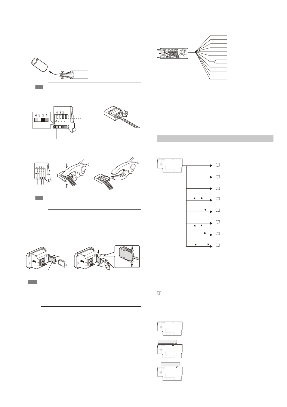
z Power/Input-output cable
The following information shows the details of power/Input-output cable. For information
about the input-output circuit, see page 9 of this Instruction Manual.
*1
IG-1050/IG-1550 (expansion unit) do not have brown, blue, or light blue wires.
Power is supplied to the expansion units through IG-1000/IG-1500 (main unit).
*2
The Analog output can be set for the following: “Not used (OFF), 0 - 5 V, ±5 V, 1 - 5 V
and 4 - 20 mA”.
Please reference, “Operation When the Power is Turned on for the First Time” (page 6)
and “Initial Reset (Initialize)” (page 7)
*3
In addition to the selections noted on the pictorial above, the External inputs can also
be selected to perform the following: Bank A, Bank B, Laser emission stop input and
Not used (OFF). The Gain input can be selected only for the external input 4.
For details, refer to the User’s Manual.
Amplifier functions and displays
Setting method
Basic display
Basic display
z R.V. (internal measurement value) and P.V. (judgment value)
R.V. (internal measurement value) means the value displayed when the desired object to be
measured is inserted into the measurement range.
* R.V. = Raw Value
P.V. (judgment value) is the value associated with the output state (ON or OFF) depending
on the tolerance setting value. Also, the analog output is based on the P.V. value.
* P.V. = Present Value
“Setting the Tolerance Setting Value” (page 6)
The P.V. (judgment value) and R.V. (internal measurement value) are basically the same,
however, those values differ when the hold function and calculation function are used.
z Main display
P.V. (judgment value) is displayed on the main display.
Note
Do not strip the core wire insulation.
Note
Once the connector has been installed, make sure to connect it to the
amplifier and confirm that the sensor operates normally.
Once the connector is crimped, it cannot be reused.
Note
• The number of core wires for the power/Input-output cable for the main
unit is 12, and the number of core wires for the Input-output cable for the
expansion units is 8.
• Power for the expansion units is supplied from the main unit.
• If the input-output cable is not used for the expansion units, cut the cable
at the connector base, or terminate them separately for future use.
Brown
Black
White
Blue
Insert further
than here.
Power/Input-output cable
To attach
To remove
“Registering the standard waveform” (page 6)
“Basic setting” (page 8)
“Initial Reset (Initialize)” (page 7)
"Setting the measurement sensitivity",
refer to the User's Manual
"Calculation function", refer to the User's
Manual
"Bank switching function", refer to the
User's Manual
"Calibration function", refer to the User's
Manual
"Key lock function", refer to the User's
Manual
Normal
The same value as the R.V. (internal measurement value) is
displayed and the output will send its signal based on the value.
When the hold function is being used
The held value is displayed and the output will send its signal
depending on the value.
For details, refer to the User’s Manual.
When the calculation function is used
Main unit
: The calculation result with expansion units is
displayed and the output will send its signal
depending on the value.
Expansion units : The P.V. (judgment value) on the expansion unit
alone is displayed and the output will send its
signal depending on the value.
Brown
Blue
Black
White
Gray
Light blue
Orange
Shield
Pink
Yellow
Pink/Purple
Purple
Green
DC10-30 V
0 V
HIGH judgment output
LOW judgment output
GO judgment output
Analog output +
Analog output GND
External input 1 (Zero shift input)
External input 2 (Reset input)
External input 3 (Timing input)
External input 4 (Not Used)
Edge check output
*1
*1
*1
*2
*2
*3
*3
*3
*3
LASER
BANK
0
1
2
3
HI
GO
LO
R.V. ANALOG
HI
SHIFT
ZERO SHIFT
TIMING
LO
ALIGNMENT
HOLD
CALC
CHECK
Press [MODE] and [SET] for 2 seconds.
Press [SET] for 5 times.
Press [MODE] for 2 seconds.
or
Press for 2 seconds.
Press for 2 seconds.
Press for 2 seconds.
Press for 2 seconds.
While pressing [MODE]
While pressing [MODE]
[MODE] and , or [MODE] and
and
[MODE] and
[MODE] and
LASER
BANK
0
1
2
3
HI
GO
LO
R.V. ANALOG
HI
SHIFT
ZERO SHIFT
TIMING
LO
ALIGNMENT
HOLD
CALC
CHECK
LASER
BANK
0
1
2
3
HI
LO
R.V.
ANALOG
HI
SHIFT
ZERO SHIFT
TIMING
LO
ALIGNMENT
[HOLD] lights up.
GO
HOLD
CALC
CHECK
LASER
BANK
0
1
2
3
HI
LO
R.V.
ANALOG
HI
SHIFT
ZERO SHIFT
TIMING
LO
ALIGNMENT
HOLD
CALC
CHECK
GO
[CALC] lights up.