Switch faults – Cub Cadet RZT-S Zero Electric User Manual
Page 92
RZT-S Zero
88
Switch faults
The VCM sends 5 volts out pin 8 of the 16 pin connector. This 5 volts goes to the:
•
Charger door switch
•
Brake switch
•
TPS assembly
•
Steering sensor
•
PTO switch
•
Seat switch (via the charger door switch)
NOTE: The TPS, charger door, seat and PTO switches have dual circuits as a redundancy and are considered
critical safety inputs.
NOTE: The charger door switch is considered a critical safety switch and gets its redundancy by splitting its
output. The output goes to the VCM but has a branch that goes to the seat switch. The branched circuit
supplies the power to the seat switch circuit. If the charger door circuit is open, the VCM will have 0
volts for both the charger door and the seat switch circuits. The charger door switch is a higher priority
than the seat switch, so only the charger door message will appear on the display.
Seat switch
The seat switch receives 5 volts from the charger door switch through a brown wire (early production units
may have a red wire with a white trace). That wire goes to pin 2 of the seat switch connector and is jumped to pin 4.
Pins 1 and 3 are independent return paths to the VCM. The orange wire goes to pin 4 of the 16 pin VCM connector
and the orange wire with a white trace goes to pin 3.
NOTE: Both the orange wire and the orange wire with a with trace have a diode in them that prevents a back
feed from the VCM.
If there is a seat fault:
NOTE: The charger door circuit must be functioning
properly before testing the seat switch cir-
cuit.
1.
Inspect the seat switch connection.
2.
Remove the VCM by following the procedures
described in the Vehicle Control Module (VCM) sec-
tion of this chapter.
3.
Install the harness break out adapters.
4.
Turn the key switch to the “ON” position
5.
Set a DMM to measure DC volts.
6.
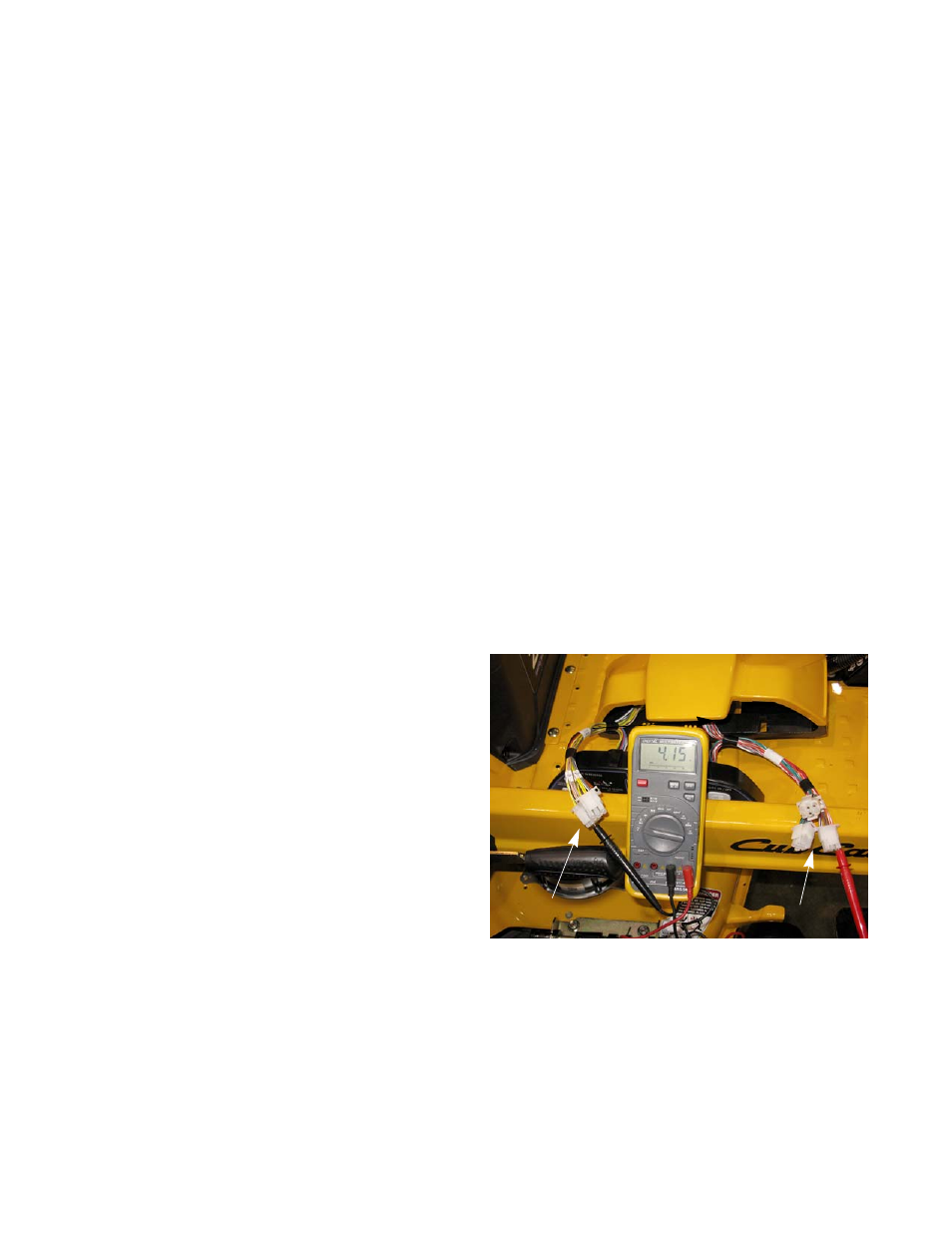
Measure the voltage from pin 7 of the 12 pin con-
nector to pin 3 of the 16 pin connector.
See Figure 5.60.
7.
Measure the voltage from pin 7 of the 12 pin connector to pin 4 of the 16 pin connector
•
If the DMM reads 4 - 5 volts, at both locations the VCM is faulty.
Figure 5.60
12 pin adapter
16 pin adapter