Cub Cadet RZT-S Zero Electric User Manual
Page 55
Steering
51
To install a drag link:
1
Install the jam nuts on the new drag link.
NOTE: Thread the jam nuts all the way to the unthreaded
section of the drag link.
2.
Install the ball joint ends on the drag link.
NOTE: The ball joint ends should be threaded on to the
drag link the same number of turns as was
required to remove the old ones.
3.
Remove both of the yoke covers.
4.
Attach the outer ball joint to the inboard sector gear.
5.
Manually turn the front wheels to the straight forward
position.
6.
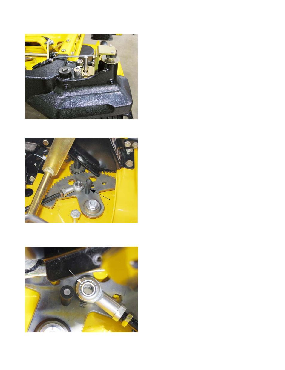
Install the 5/16” alignment pins in the axle castings.
See Figure 4.28.
7.
Turn the steering wheel to bring the sector gears to
the center (neutral) position.
NOTE: Install the 1/4” alignment pin to insure that the sec-
tor gears are in the neutral position.
See Figure 4.29.
8.
Adjust the ball joints on the threaded drag links to
align them with the holes in the segment gears.
See Figure 4.30.
9.
Install the nuts and bolts that attach the drag links to
the segment gears.
10. Tighten the drag link ball joint jam nuts.
11. Remove all of the alignment pins.
12. Install the axle casting covers.
13. Install the floor pan by following the procedures
described in Chapter 3: Body.
14. Test drive the mower in a safe area before returning
it to service.
NOTE: Do not put a mower back into service if it does not
react properly to control inputs.
Figure 4.28
Alignment pin
Figure 4.29
Alignment pin
Figure 4.30
Holes aligned