Cub Cadet RZT-S Zero Electric User Manual
Page 89
Electrical System
85
To determine if the contactor assembly is functioning prop-
erly:
1. Remove the left pod by following the procedures
described in Chapter 2: Body.
NOTE: Do not disconnect the battery pack while removing
the pod.
2.
Install a jumper in the charger door switch connector.
3.
Install the 12 pin harness breakout adapter between
the harness and the contactor assembly.
See Figure 5.52.
4.
Remove the controller covers
5.
Set the parking brake.
6.
Turn the key switch to the “ON” position.
7.
Set a DMM to measure DC volts.
8.
Measure the voltage across the positive and negative
wires at each controller. See Figure 5.53.
• Each controller should have battery voltage.
A. If any controller has 0 volts, the fused power lead has
blown due to a short. Repair the short then replace
the control panel.
B. If all of the controllers read 0 volts, the pre-charge
signal is not reaching the controllers.
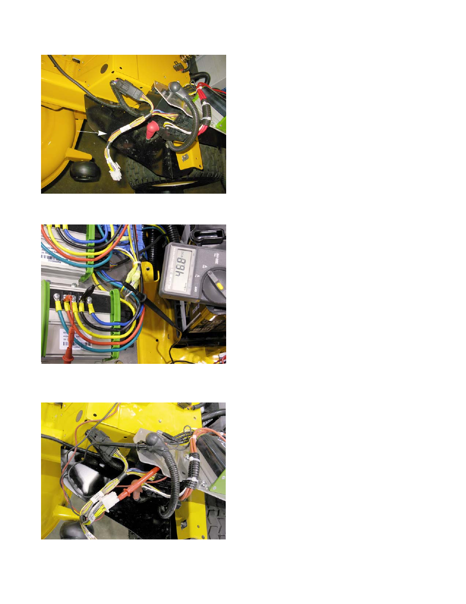
1. Place the positive probe in pin 4 of the breakout
adapter. See Figure 5.54.
2.
Place the negative probe on the master ground bus
3.
While sitting in the seat with key switch in the “ON”
position, depress the start button while watching the
DMM.
• The DMM should read battery voltage. If the DMM
measures 0 volts, the contactor is not getting the
pre-charge voltage from the VCM.
• If the DMM reads battery voltage, the contactor
assembly is faulty, replace the control panel.
Figure 5.52
Break out
adapter
Figure 5.53
Figure 5.54