Cub Cadet RZT-S Zero Electric User Manual
Page 65
Electrical System
61
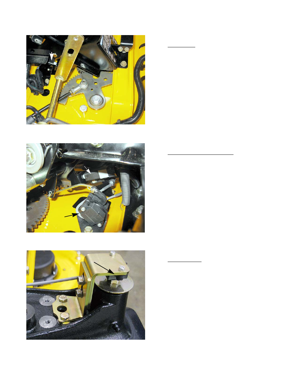
• Brake switch: The brake switch is a SPDT switch
with one set of contacts that are Normally Open
(N.O.) and the other set of contacts that are Nor-
mally Closed (N.C.). See Figure 5.10.
NOTE: The red wire with a white trace carries a 5 volt sig-
nal to one of the NC tabs of the brake switch.
When the brake pedal is released, a voltage signal
will pass through the brake switch and flow to the
VCM through the brown wire with a white trace.
• Throttle Position Sensor (TPS): The TPS sensor is
actually an assembly of two rotary hall effect sen-
sor mounted together. See Figure 5.11.
NOTE: The TPS receives power, 5 volts, through the red
wire with a white trace. The voltage returns to the
VCM (negative voltage) through the green wire
with a black trace. The green wire and the green
wire with a white trace are the input signals to the
VCM.
NOTE: The TPS must be calibrated anytime the sensor is
disconnected, removed or replaced.
• Steering sensor: The steering sensor is a hall
effect sensor that measures the rotation of a mag-
net in the head of the bolt that holds the left front
yoke in place. See Figure 5.12.
NOTE: The steering sensor receives 5 volts through the
red wire with a white trace. The voltage returns to
the VCM through the blue wire with a black trace.
The input signal is carried to the VCM through the
blue wire.
NOTE: If the VCM senses a fault in the steering sensor
input, it will disable the deck motors and lower
ground speed of the mower while showing a fault
code.
NOTE: The steering sensor must be calibrated anytime
the switch is removed or replaced.
Figure 5.10
Brake switch
Figure 5.11
TPS
Brake switch
Figure 5.12
Steering sensor