Cabletron Systems 2H23-50R User Manual
Page 38
Chapter 3: Installation
3-12
2H23-50R/2H33-37R User’s Guide
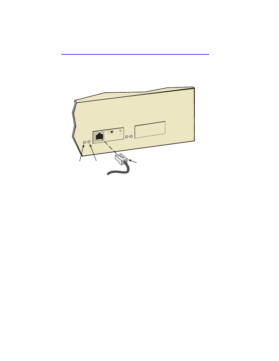
2.
Connect the twisted pair segment to the module by inserting the RJ45
connector on the twisted pair segment into the RJ45 port on the
module shown in
Figure 3-9
FE100-TX Port Connection
3.
Verify that a link exists by checking that the port RX LED is on
(flashing amber, blinking green, or solid green). If the RX LED is off
and the TX LED is not blinking amber, perform the following steps
until the RX LED is on:
a.
Verify that the 100BASE-TX device at the other end of the twisted
pair segment is powered up.
b.
Verify that the RJ45 connector on the twisted pair segment has the
proper pinouts.
c.
Check the cable for continuity.
d.
Make sure that the twisted pair connection meets the cable
specifications outlined in
e.
Confirm that the crossover switch is in the correct position.
If a link is not established, contact the Cabletron Systems Global Call
Center. Refer to
22861-14
TX LED
RJ45
RX LED
FE-100TX
10
100
x
=
6
5