BUCHI Inert Loop B-295 User Manual
Page 26
4 Description of function
26
B-290 Operation Manual, Version I
4 .7 .1
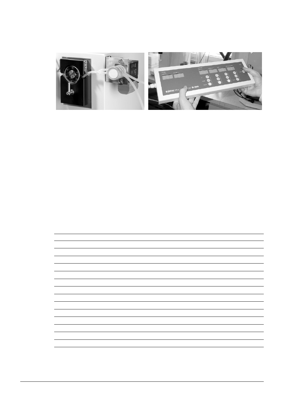
Feed switch valve and remote control panel
Fig. 4.7: Feed switch valve and remote control panel
The remote control panel enables an easy operation even within a closed fume hood. The flow meter
for the spraying gas is the only parameter which cannot be adjusted via the remote control panel.
The feed switch valve is a useful tool together with the remote control panel. During the start and end
of the spray process, the feeding tube has to be moved from pure solvent to product solution and
vice versa. This can be automated by means of the feed switch valve. A Y-piece is inserted between
peristaltic pump and feed switch valve.
4 .7 .2
Printer or PC for data output via RS-232 serial port
The Mini Spray Dryer B-290 is supplied with a standard protocol for data readout. This is of special
importance if the system is qualified and underlies special regulations.
The connection starts as soon as the heater is switched on.
The transmission rate is 2400 Baud/s, Parity: No.
The parameters are sent out every 30 seconds as an ASCII-Code, separated by a TAB (ASCII 09)
and ended with a RETURN (ASCII 0D). They can be read out e.g. via the program “HyperTerminal”
included in the Microsoft package.
The source is defined as follows:
No.
Information
Type
Unit
1
Time since mains on
integer
s
2
Current temperature inlet
integer
°C
3
Current temperature outlet
integer
°C
4
Heater on/off
0/1
5
Set temperature inlet
integer
°C
6
Aspirator on/off
0/1
7
Aspirator rotation speed
integer
%
8
Pump on/off
0/1
9
Pump rotation speed
integer
%
10
Feed switch valve
1/2
11
Connection Inert Loop B-295 no/yes
0/1
12
Oxygen high
0/1
13
Pressure low
0/1
14
Error message
integer