Alarm i/o – DVR systems NVR38xx Series User Manual
Page 110
110
Parameter Function
Normal
Out
The corresponding alarm output channel when alarm occurs.
For 1U series product, there are three channels.
For 2U series product, there are six channels. The 6
th
channel is the
controllable +12V alarm output.
Latch
The alarm output can delay for the specified time after alarm stops. The
value ranges from 10s to 300s.
Record
channel
After you selected the disk connection option, once the device is offline,
the activated channel can begin alarm record.
Record
latch
System can delay the record for specified time after alarm ended. The
value ranges from 10s to 300s.
Send
email
If you enable this function, system can send out email to alarm the
specified user.
Show
message
Once you check the box to enable this function, system can display the
alarm icon on the right of the channel name at the local end.
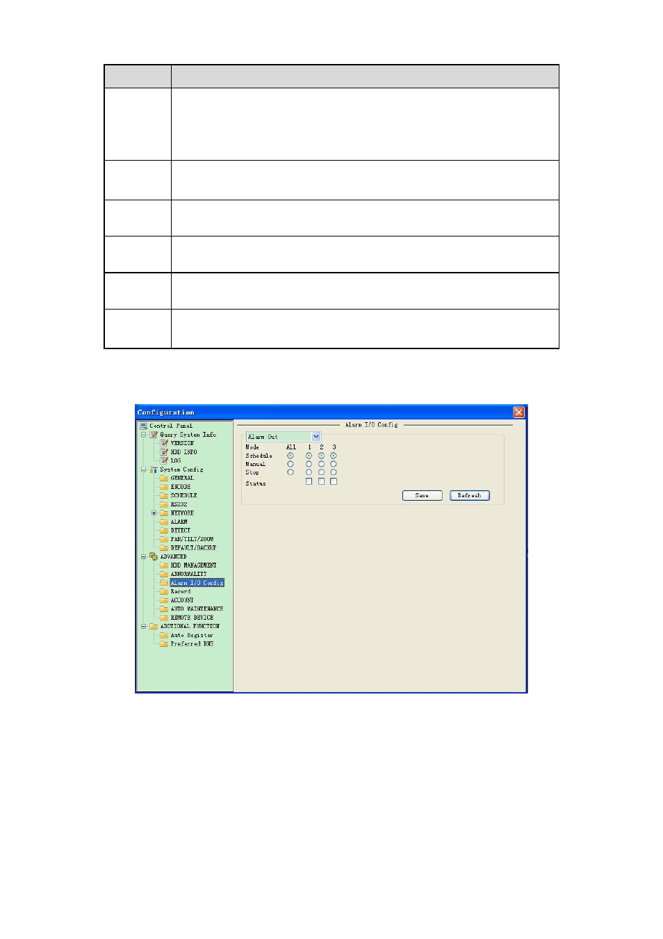
8.3.3.3 Alarm I/O
Here you can search alarm output status. See Figure 8-40.
Figure 8-40 Alarm I/O Configuration
Important
The alarm output port should not be connected to high power load directly (It shall be less than 1A)
to avoid high current which may result in relay damage. Please use the co contactor to realize the
connection between the alarm output port and the load.
Please refer to the following sheet for detailed information.