3 fiber optic diagnostic procedure, Fiber optic diagnostic procedure – CANOGA PERKINS 2240 Fiber Optic Modem User Manual
Page 89
Chapter 6 Diagnostic Procedures
Fiber Optic Diagnostic Procedure
89
6.3 Fiber Optic Diagnostic Procedure
If the Loopback Test is successful, and the modems still do not function, check the fiber optic
parameters as outlined below. There also may be a data rate incompatibility. If this check out of
the electrical and optical links provides no indication as to the problem, contact Canoga Perkins
Installation and Repair Department for assistance.
NOTE: Each range limit has a +1dB margin at the transition point.
The following are some additional checkpoints to consider about fiber optics:
•
Are you using a fiber optic link of less than the High Power Loss Budget? (Refer to
Table 6-1.) Set the optical power switch to LO.
•
Are you using a fiber optic link of more than the Low Power Loss Budget? (Refer to
Table 6-1.) Set the optical power switch to HI.
•
Are the fiber optic cables marked correctly? Connect Tx cable to Tx connector, Rx to the
Rx connector. If Local and Remote Sync indicators do not come on, try swapping cables
at one end of link.
•
Is the data rate set correctly?
•
Are you using the correct clock mode (internal/external) for synchronous transmission or
are you using asynchronous transmission?
NOTE: The 1310 nm LP laser does not have a HI/LO power switch.
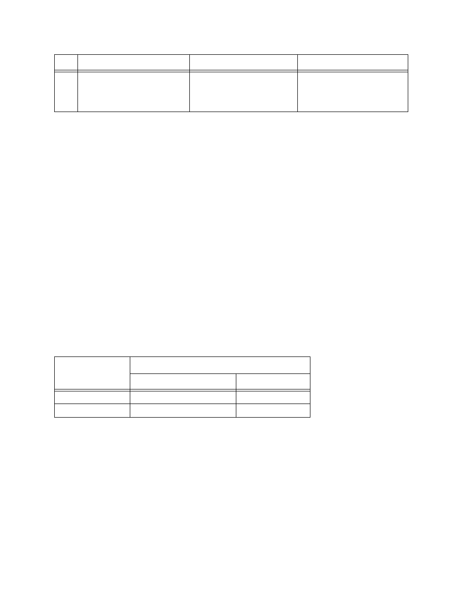
9
Set the Local Loopback switch
on the near-end modem.
Modem fails BERT when looped
locally.
Defective modem or electrical
interface.
Replace defective modem.
Table 6-1. Link Loss Range
Model
Link Loss Range
HI Power
LO Power
850 nm Standard
>6 dB to Max
<6 dB
1310 nm HP laser
>6 dB to Max
<6 dB
Step
Symptom
Possible Cause(s)
Action