7 setting up a tail circuit, Setting up a tail circuit – CANOGA PERKINS 2240 Fiber Optic Modem User Manual
Page 26
2240 Fiber Optic Modem User Manual
Chapter 2 Installation and Setup
Setup
26
Figure 2-3 Extra Clock Pins in a Tail Circuit Application at Clock Source End
NOTE: X equals the extra clock input pins on the enhanced interfaces. "Extra
clock" jumper would have to be ON at this 2240.
NOTE: Control lead crossovers are not shown for clarity.
NOTE: The 2240 in the diagram would be operating in Mode 7, with rate set to
match CSU/DSU speed. The 2240 at far end would be operating in slave
mode.
2.1.7 Setting Up a Tail Circuit
This section covers setting up a tail circuit.
NOTE: When the customer-supplied clock is within certain ranges, this mode
allows transmission of clock and data signals with minimal jitter. In the
Locked mode, the entire transmitter section of the 2240 is locked to the
clock provided by the DTE. The Locked mode is always used for T1
(1.544 Mbps), E1 (2.048 Mbps), and any synchronous data transmission
between 1.490 Mbps and 2.060 Mbps. Locked mode is also possibly at
lower speeds if the customer's equipment cannot tolerate the pulse jitter of
the sampled external clock mode.
Use the following switch settings for the local site.
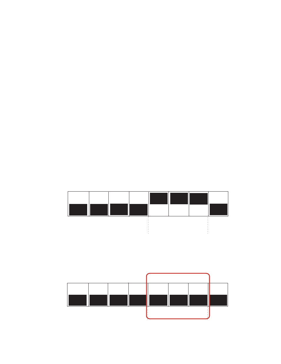
Figure 2-4 Switch Settings for the Remote Site
Use the mode switch settings below for the tail end to set it to slave clock (mode 5).
1
7
3
4
5
6
8
2
OPEN
CLOSED
RATE SWITCHES
MODE
RANGE
SELECT
(RATE 0 / MODE 7 / ORIGINAL RANGE SHOWN)
1
7
3
4
5
6
8
2
OPEN
CLOSED
RATE SWITCHES
MODE
RANGE
SELECT