2 rack-mount modem installation, 3 fiber cable and connectors, 4 2202 modem shelf installation – CANOGA PERKINS 2240 Fiber Optic Modem User Manual
Page 28: Rack-mount modem installation, Fiber cable and connectors, 2202 modem shelf installation
Chapter 2 Installation and Setup
2240 Fiber Optic Modem User Manual
Installation
28
2.2.2 Rack-Mount Modem Installation
The 2201 Rack Chassis is designed for installation in a standard 19-inch wide equipment rack.
Tabs are provided on each side of the unit, and are predrilled for standard spacing. Refer to the
2201 Rack Chassis User Manual for more information on installing a 2201.
When installing a modem or panel, the Nylatch retainer should be in an outward, or released
condition. Slide the modem card into the rack until it engages fully with the PC board edge
connector, then push the Nylatch retainers in.
For each modem installed, compatible communications cables and appropriate fiber optic cables,
terminated with the appropriate type connectors, will be required.
2.2.3 Fiber Cable and Connectors
The Transmit (Tx) from the local modem should be connected to the Receive (Rx) at the remote
modem and the Receive (Rx) from the local modem should be connected to the Transmit (Tx) at
the remote modem.
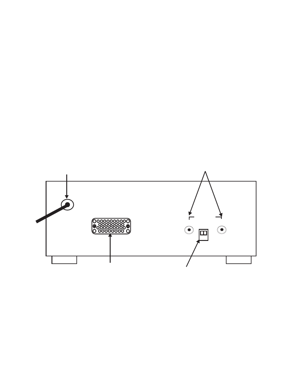
The connectors are clearly marked as to their function, either Transmit (Tx) or Receive (Rx) on
the back panel of the 2240 standalone units. Figure 2-6 shows with the V.35 Interface.
Figure 2-6 2240 Standalone Rear Panel Layout
2.2.4 2202 Modem Shelf Installation
The 2202 Modem Shelf is mounted in an equipment rack. Two 2200 Series standalone modems
can be installed in the 2202, side-by-side on the shelf. Refer to the 2202 Modem Shelf User
Manual for more information about installation.
OPTICAL
OPTICAL
HI
HI
LO
LO
TX
TX
RX
RX
V.35 INTERFACE
V.35 INTERFACE
POWER ENTRY
POWER ENTRY
ELECTRICAL
ELECTRICAL
DATA INTERFACE
DATA INTERFACE
HI/LO TX
HI/LO TX
POWER SWITCH
POWER SWITCH
FIBER OPTIC
FIBER OPTIC
CONNECTORS
CONNECTORS