10 ccitt v.35/mrc 34 interface, Ccitt v.35/mrc 34 interface – CANOGA PERKINS 2240 Fiber Optic Modem User Manual
Page 60
Chapter 4 Data Interfaces
2240 Fiber Optic Modem User Manual
Multi-Channel Interfaces
60
4.6.10 CCITT V.35/MRC 34 Interface
This interface complies with CCITT Standard V.35 and ISO 2593-1993. Electrical characteristics
comply with V.35 for clock and data signals and RS-232 levels for control signals.
This interface uses the physical connector type and pinouts specified in ISO 2593-1993 (refer to
Table 4-12). The V.35 interface uses a 34-pin female Winchester connector for the physical
connection.
Note that the table lists the function name shown in ISO 2593 and an aka where applicable. The
rest of this section refers to the ISO 2593 function name and aka interchangeably. For example,
the aka Serial Clock Transmit (SCT) is the same as ISO 2593 Transmitter Signal Element Timing.
The TXD, RXD, SCT, SCR and SCTE pins carry the primary data and clock signals (conforming
to the V.35 standard). In addition, an extra clock signal input is provided to make the 2240/-MC2
combination more "DTE-like" in tail circuit applications at the clock source end. The remainder of
the pins are either ground references or control signals. Transmit Data (TXD) and Receive Data
(RXD) are the data input and output signals for the modem, respectively.
Serial clock Transmit (SCT) is the modem’s transmit clock reference output that is used for the
internal and slave clock modes. Serial Clock Receive (SCR) is the clock signal for the receive
data unless the 2240's main PCBA W26 (XTCLK) jumper is ON, in which case the Extra Clock
input signal is used to shift receive data out from the 2240. Serial Clock Transmit External
(SCTE) is the transmit clock signal used in either of the External clock modes or when the main
board's internal CLK/EXT switch is set to EXT (refer to section 3.7).
Two end-to-end control leads are provided as part of this interface. An input to RTS is transmitted
to the DCD output at the other end of the link (see description of RTS-Bias jumper and DCD
jumper). CTS (Clear to Send) follows RTS locally but is delayed approximately 1 millisecond
when RTS turns ON (see description of CTS-Gate jumper). The other end-to-end control lead
pair is listed below with the input signal listed first:
•
DTR to RI
This path, in conjunction with crossover cables at the DTR end, can be used to implement
incoming call handshaking.
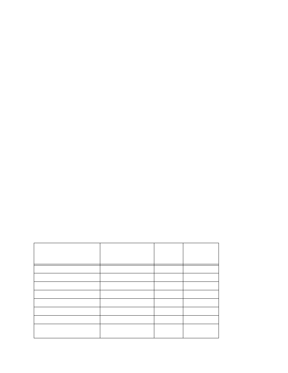
Table 4-12. CCITT V.35 Pinouts for MC2
Function
Pin (A/B)
CCITT
Circuit
Number
Direction
Shield
A
101
–
Signal Ground
B
102
–
Request to Send (aka RTS)
C
105
to modem
Clear to Send (aka CTS)
D
106
from modem
Data Set Ready
E
107
from modem
Data Channel Receive Line
F
109
from modem
Signal Detector (aka DCD)
Data Terminal Ready (aka
DTR)
H
108
to modem