1 jumper and switch settings, Jumper and switch settings – CANOGA PERKINS 2240 Fiber Optic Modem User Manual
Page 71
Chapter 4 Data Interfaces
Programmable Buffered Interface/Model P53
71
4.9.1 Jumper and Switch Settings
All jumper settings and descriptions are listed in Table 4-18. This interface has strap option
jumpers to configure the RLSD Output at J1-8 (DB-25) to support the KG-194 Resync capability.
Jumper straps W10/W11 (adjacent to U11) and W12/W13/W14 (adjacent to U8) implement this
function (refer to Table 4-18 and Figure 4-6). Jumper straps W10/W11 control the ON/OFF level
and W12/W13/W14 configure the RLSD Output to Bipolar (+6 V and -6 V) or single-ended (+6
and 0 or -6 and 0).
The W1/W2 strap connects chassis ground to signal ground (W2 position), connects chassis
ground through 100 ohms to signal ground (W1 position), or isolates chassis ground from signal
ground (jumper out). The W5, W6 and W7 jumpers, when installed, ground the midpoints of the
100 ohm termination resistances of the FIFO CLK, SCTE and TxD line receivers. These jumpers
may provide improved performance in cases where the RS-422 inputs are bipolar rather than the
more common unipolar types. The W8, W9 and W15/W16 jumpers are used for converting to the
Legacy configuration (see Figure 4-15).
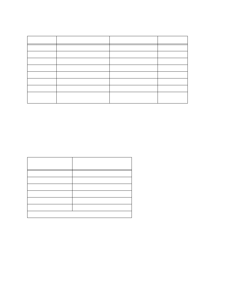
Table 4-18. Jumper Settings and Descriptions
Jumper
Description
Notes
Factory Setting
W1/W2
Chassis Ground
W1 - 100 ohms/W2 - Short W1 Default
W5/W6/W7
RCVR Terminations
All Out
W8/W9
Legacy Config.
Both Out
W10/W11
RLSD Output Swing
W11
W12/W13/W14
RLSD Output Swing
W13
W15/W16
DSR
W15 - Test/W16 - GND
W16 Default
W17/W18
RTS Bias
W17 - On/W18 - Off
W18 Default
W19/W20
RLSD
W19 - Single Ended/
W20 - Differential
W20 Default
Table 4-19. Strap Configurations for RLSD (CD) Output
Strap Configurations
CD Output (at J1-8**)
Voltage Level ±1 V On/Off
W11 and W14
+6/-6
W11 and W12
+6/0
W11 and W13
0/-6
W10 and W14
-6/+6
W10 and W12
0/+6
W10 and W13
-6/0
** J1-6 when using the "Legacy" (P2) Converter