9 programmable buffered interface/model p53, Programmable buffered interface/model p53 – CANOGA PERKINS 2240 Fiber Optic Modem User Manual
Page 67
Chapter 4 Data Interfaces
Programmable Buffered Interface/Model P53
67
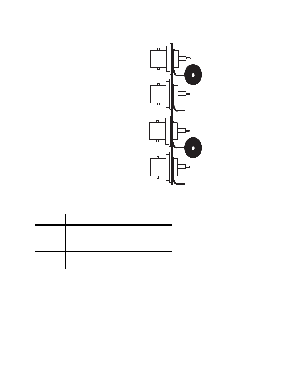
Figure 4-4 BNC Connectors
4.9 Programmable Buffered Interface/Model P53
The Model P53 Interface Module complies with EIA Standard RS-530 while all clock, data and
control signals follow the RS-422 standard. The basic configuration of the P53 interface is a DCE
device (w/Fem DB-25) and two connector adapters are provided with the interface: the DCE/DTE
adapter which converts the interface to the DTE form (w/Male DB-25) and the "Legacy" adapter
which converts the interface to the original Model P2 interface.
This interface implements a set of circuits (resources) which can be interconnected in various
ways to satisfy a host of differing applications. These resources are:
•
a 16-bit FIFO (first-in, first-out) buffer
Table 4-16. BNC Supported Signals
Signal
Full Name
Direction
TxD
Transmit Data
To Modem
RxD
Receive Data
From Modem
SCR
Serial Clock Receive
From Modem
SCT
Serial Clock Transmit
From Modem
SCTE
External Clock Transmit
To Modem
Receiver Clock
Received Data
Transmitted Data
Transmitter Clock
External
Transmitter Clock
or