4 internal, Internal, Igure 4-11, fig – CANOGA PERKINS 2240 Fiber Optic Modem User Manual
Page 75: Chapter 4 data interfaces, Programmable buffered interface/model p53, J1(db - 25)
Chapter 4 Data Interfaces
Programmable Buffered Interface/Model P53
75
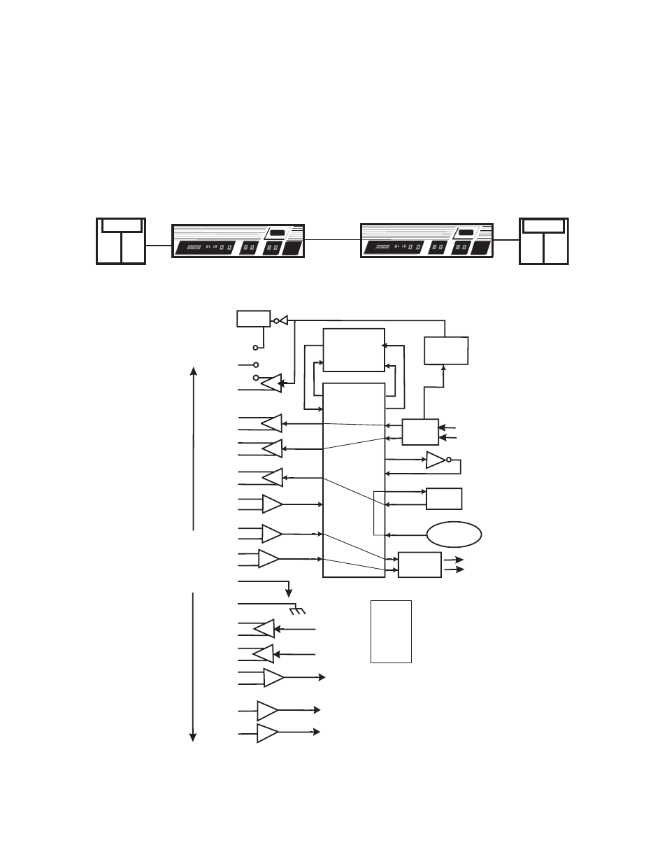
4.9.4 Internal
The internal function is used when network equipment is set for Eternal Timing (see Figure 4-10
and Figure 4-11). When connecting KG or KIV encryptors together on the Black side, you should
install the internal strapped header in the J3 position. In this application, the modems are acting
as the network timing source. In most cases, both modems should be set for internal master
clock. The rate switches should be set to the appropriate speed for the circuit. This header is
provided with the interface. The figures below show a typical internal clock application.
Figure 4-10 Internal Programmable Buffered Interface, Model P53, DCE RS-530
Figure 4-11 Internal Programmable Buffered Interface, Model P53
CANOGA
CANOGA
PERKINS
PERKINS
Data
Data
Rx
Rx
Tx
Tx
Clock
Clock
Rate mode
Rate mode
Pwr
Pwr
Loop
Loop
On
On
Rem/Loc
Rem/Loc
2270
2270
Fiber
Fiber
Modem
Modem
Optics
Optics
TX
TX
RX
RX
Off
Off
CANOGA
CANOGA
PERKINS
PERKINS
Data
Data
Rx
Rx
Tx
Tx
Clock
Clock
Rate mode
Rate mode
Pwr
Pwr
Loop
Loop
On
On
Rem/Loc
Rem/Loc
2270
2270
Fiber
Fiber
Modem
Modem
Optics
Optics
TX
TX
RX
RX
Off
Off
MM or SM
Fiber Optics
KG/KIV
RED BLK
KG/KIV
RED
BLK
RLSD
KG Swing
Jumpers
Internal
Clock From
Modem
Rx Data
Tx Clock
Tx Data
Modem
Alarm
Function
From
Fiber
Circuits
To
Fiber
Circuits
Delay
Line
Inverter
FIFO
Data Out Data In
Shift Out Shift I
n
W19
W20
8
10
3
16
17
9
12
15
SG
FG
CTS
DSR
RTS
FIFO
Clock
SCTE
TxDxD
From Modem
To Modem
To Modem
5
12
19
13
14
16
17
18
3
4
9
6
1
2
11
10
15
7
8
20
23
24
11
2
14
LL
RL
SCT
RxD
SCR
IN
OUT
J1(DB - 25)
7
1
5
13
22
19
18
21
6
4
P/N 6100030-005
Wire Wrap
Net List
6-13
7-17
8-18
9-19
10-14
11-15