8 rs-423/db-25 interface, Rs-423/db-25 interface – CANOGA PERKINS 2240 Fiber Optic Modem User Manual
Page 58
2240 Fiber Optic Modem User Manual
Chapter 4 Data Interfaces
Multi-Channel Interfaces
58
cable. If this ground connection is present, and you prefer to use it, move the UNBAL_REF
jumpers to SC.
Factory setting: GND
4.6.8 RS-423/DB-25 Interface
NOTE: The maximum data rate for this interface is 9.6 kbps.
This interface is electrically compatible with EIA RS-423A. It will also operate with asynchronous
RS-232D systems.
This interface uses the physical connector type and pinouts specified in RS-232D (refer to
Table 4-10). The RS-423/232D interface uses a 25-pin, female D-type connector for the physical
connection.
There are six end-to-end control lead pairs. They are listed with the input signal listed first.
•
TD to RD
•
STD to SRD
•
DTR to RI
•
SRTS to SDCD
•
DSRS to SCTS
•
RTS to DCD
NOTE: If DTR to RI and STD to SRD are used on the RS232/RS366 port, these
control leads may not be available on 422/449 and V.35 interfaces.
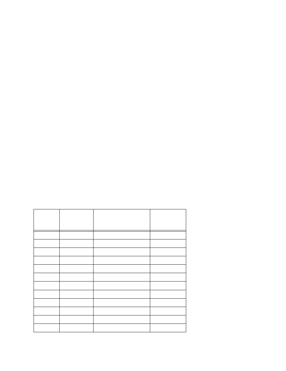
Table 4-10. RS-423 Pinouts for Models MC1 and MC2
Pin
Number
RS-232 Pin
Name
(abbrev)
(full name)
Direction
1
PG
Protective Ground
–
2
TD
Transmit Data
to modem
3
RD
Receive Data
from modem
4
RTS
Request to Send
to modem
5
CTS
Clear to Send
from modem
6
DSR
DCE Ready
from modem
7
SG
Signal Ground -
–
8
DCD
Receive Line Sig. Det.
from modem
12
SDCD
Secondary Line Sig. Det.
from modem
13
SCTS
Secondary CTS
from modem
14
STD
Secondary TD
to modem
16
SRD
Secondary RD
from modem