2 rs-423/232d model 432, Rs-423/232d model 432 – CANOGA PERKINS 2240 Fiber Optic Modem User Manual
Page 42
2240 Fiber Optic Modem User Manual
Chapter 4 Data Interfaces
RS-423/232D Model 432
42
4.2 RS-423/232D Model 432
NOTE: The maximum data rate for this interface, 153.6 Kbps, is limited by the
interface driver slew rate.
This interface is electrically compatible with EIA RS-423A. It will also operate with RS-232D
systems when adhering to the more limiting RS-232D specifications (20 kbps and 2500 pF cable
capacitance). EIA standard RS-423A does not reference physical connector types or pinouts.
This interface uses the physical connector type and pinouts specified in RS-232D (refer to
Table 4-2). The RS-423/232D interface uses a 25-pin female D-type connector for the physical
connection.
The TD, RD, SCT, SCR and SCTE pins carry the primary clock and data signals. The remaining
pins are either ground references or control signals.
Transmit Data (TD) and Receive Data (RD) are the data input and output signals for the modem.
Serial Clock Transmit (SCT) is the modem’s transmit clock output used for the internal and slave
modes. Serial Clock Receive (SCR) is always the clock signal for the Receive Data. Serial Clock
Transmit External (SCTE) is the clock signal input used in External Clock Mode.
None of the control leads interact with the data transmission. The control leads are provided in
order to comply with a variety of DTE interface requirements. Most of the control leads are
actually end-to-end signal channels which can be used for any purpose as long as it conforms to
the electrical interface standards of RS-232D or RS-423A. One example of this would be
asynchronous data transmission at rates up to 19.2 kbps (30% jitter due to sampling at 64 kHz).
The RTS, CTS and DCD pins function together to provide the most common handshake
functions. An input to RTS (see description of RTS-Bias jumper) is transmitted to the DCD output
at the other end of the link (see description of DCD jumper). CTS follows RTS locally but it is
delayed by approximately 1 msec when RTS turns ON (see description of CTS-Gate jumper).
There are four other end-to-end control lead pairs. They are listed below with the input signal
listed first:
•
STD to SRD
•
SRTS to SDCD
•
DTR to RI
•
DSRS to SCTS
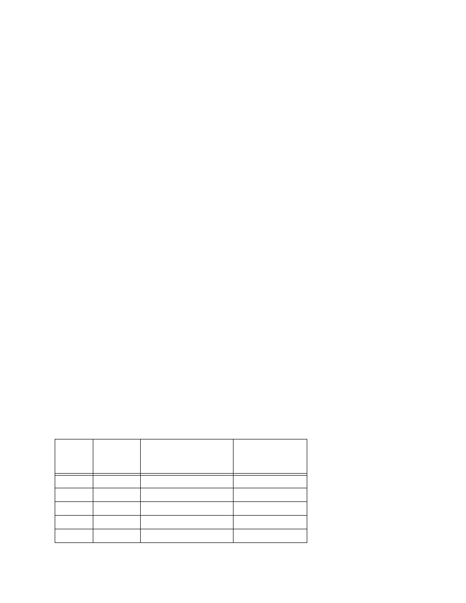
Table 4-2. RS-232D Pinouts
Pin
Number
RS-232D
Pin Name
(abbrev)
Full Name
Direction
1
PG
Protective Ground
-
2
TD
Transmit Data
to modem
3
RD
Receive Data
from modem
4
RTS
Request to Send
to modem
5
CTS
Clear to Send
from modem