1 carrier detect (cd) signal options, Carrier detect (cd) signal options – CANOGA PERKINS 2240 Fiber Optic Modem User Manual
Page 23
Chapter 2 Installation and Setup
Setup
23
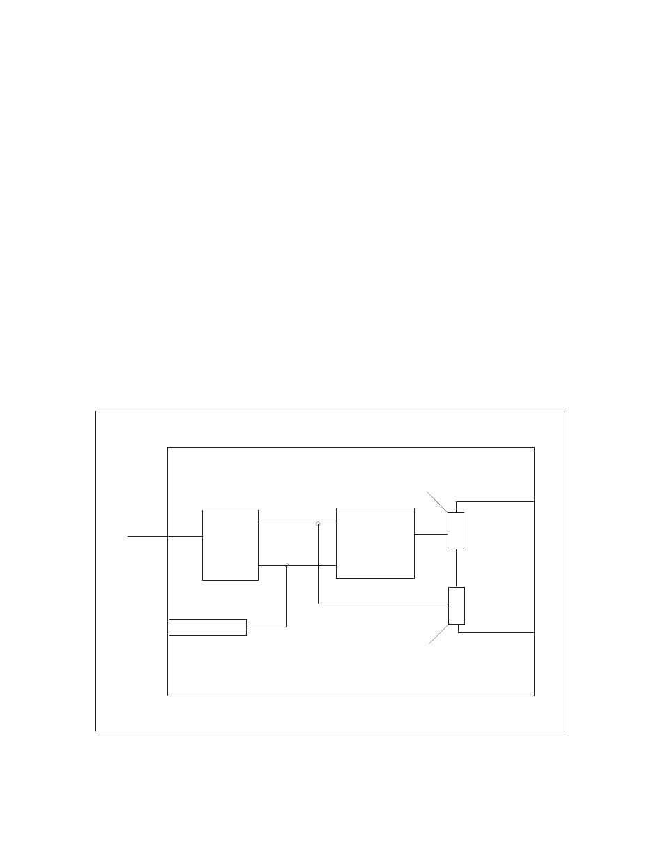
2.1.3.1 Carrier Detect (CD) Signal Options
There are two switches on the internal switch block which control the response of the CD signal
on the Standard Data Interfaces. These switches operate as a pair and only one switch should be
set to ON at any time.
Factory settings:
•
CD/DCD set to OFF
•
CD/SYNC set to ON
The CD signal can be used as an output for an end-to-end Control Channel by setting the CD/
DCD switch to ON and the CD/SYNC switch to OFF. This setting is used only with Standard Data
Interfaces that do not support the expanded interface connector on MC1 and MC2.
The factory setting causes the standard data connector CD signal to track the state of the
modem’s optical receive synchronizer. CD will assert when the modem is in local sync. This also
means that CD will track the state of the front panel Local Sync LED.
On expanded data interfaces, the standard data connector CD signal in the CD = local sync
mode (factory setting) can be used to gate CTS (or its equivalent signal) OFF when the modem’s
receiver is out of sync. See Figure 2-2 for an illustration of this factory setting.
Refer to the sections on the RS-449/422, RS-530, V.35, MC1 and MC2 interfaces for more
information about the CD-CTS gating function.
Figure 2-2 Factory Setting for CD/DCD or CD/SYNC Switches
CD/DCD
(DCD = RTS from
far end)
or CD/SYNC
selector switches
Optical
Receiver
Rx Fiber
Front Panel LED
J2
J3
To
Interfaces
J2 = Standard data
connector
J3 = Expanded data
connector
RTS from far end
Local Sync
CD