2 installation, 1 standalone modem installation, Installation – CANOGA PERKINS 2240 Fiber Optic Modem User Manual
Page 27: Standalone modem installation
Chapter 2 Installation and Setup
Installation
27
Figure 2-5 Switch Settings for Tail End
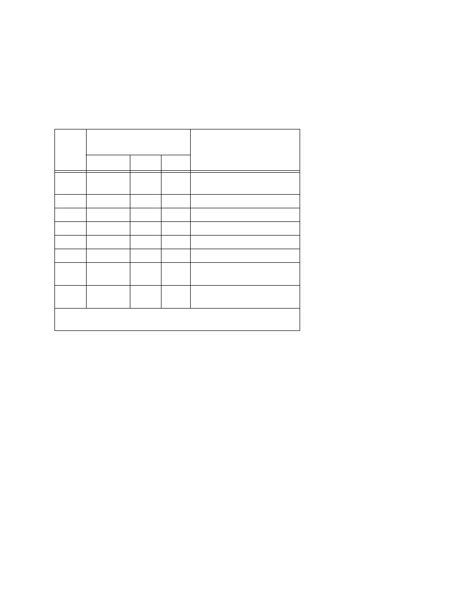
NOTE: When you are using the loopback switch for troubleshooting, set both
sides for external mode. Mode 0 is the typical external mode, see the table
below.
2.2 Installation
Installation for the 2240 Fiber Optic Modem includes unpacking the unit, and considerations for
installing the standalone and rackmount models.
2.2.1 Standalone Modem Installation
Installing the standalone version of the 2240 Modem is relatively straightforward. It should be
located conveniently to the operator and the electrical and optical cables. Fiber optics cables
should be isolated from foot traffic to prevent possible damage.
The standalone power supply, which is attached to the unit, is a wall-type transformer or in-line
for 115/230 VAC. It should be plugged into a standard AC wall outlet that incorporates a ground
line.
NOTE: The in-line transformer has a slide switch on the bottom that is used to
select the AC line voltage being used. This switch must be set correctly.
WARNING:AN INCORRECT SETTING MAY DAMAGE THE MODEM AND/OR
THE TRANSFORMER.
Table 2-2. Mode Switch Positions
Mode
DIP Switches
(C) Closed (O) Open
Operating Mode
5
6
7
0
C
C
C
Sampled External Clock up to
1.544 Mbps
1
O
C
C
Internal Clock Group 1 Rate
2
C
O
C
Internal Clock Group 2 Rate
3
O
O
C
Internal Clock Group 3 Rate
4
C
C
O
Internal Clock Group 4 Rate
5
O
C
O
Slave Clock
6
C
O
O
Asynchronous up to 1.500
Mbps *
7
O
O
O
External clock with variable
lock ratios (refer to Table 3-2)
* Frequency Limit assumes that user's equipment can tolerate 250 ns of
pulse distortion on the clock signal.