Function description, Funktionsbeschreibung, Description du fonctionnement – Pilz PNOZ X3.1 240VAC 24VDC 3n/o 1n/c 1so User Manual
Page 2
- 2 -
• The correct opening and closing of the
safety function relays is tested
automatically in each on-off cycle.
• AC relays are fitted with a short-circuit
proof power transformer. DC relays have
an electronic fuse.
Function Description
The relay PNOZ X3.1 provides a safety-
oriented interruption of a safety circuit.
When the operating voltage is supplied the
LED "Power" is illuminated. The unit is
ready for operation, when the reset circuit
S13-S14 is closed or a reset contact at
S33-S34 was opened and closed again.
• Input Circuit closed (e.g. the Emergency
Stop button is not pressed):
The status indicators for "CH. 1 IN" and
"CH. 2 IN" illuminate. Relays K1and K2
energise and retain themselves. The
safety contacts (13-14/23-24/33-34) are
closed, the auxiliary contact (41-42) is
open. The status indicator "OUT" illuminate.
• Input Circuit is opened (e.g. Emergency
Stop is pressed):
The status indicators for "CH.1 IN" and
"CH.2 IN" go out. Relays K1 and K2 de-
energise. The safety contacts (13-14/23-
24/33-34) will be opened (redundant), the
auxiliary contact (41-42) closes. The
status indicator "OUT" go out.
Semi-conductor output
The semi-conductor Y32 conducts if the
relays K1 and K2 are energised. Y32
switches off when the relays de-energise to
rest position
• Bei jedem Ein-Aus-Zyklus der Maschine
wird automatisch überprüft, ob die Relais
der Sicherheitseinrichtung richtig öffnen
und schließen.
• Der AC-Teil hat einen kurzschlussfesten
Netztransformator, der DC-Teil eine
elektronische Sicherung.
Funktionsbeschreibung
Das Schaltgerät PNOZ X3.1 dient dem
sicherheitsgerichteten Unterbrechen eines
Sicherheitsstromkreises. Nach Anlegen der
Versorgungsspannung leuchtet die LED
"Power". Das Gerät ist betriebsbereit, wenn
der Startkreis S13-S14 geschlossen ist oder
ein Startkontakt an S33-S34 geöffnet und
wieder geschlossen wurde.
• Eingangskreis geschlossen (z. B. N ot-Halt-
Taster nicht betätigt):
Die Statusanzeigen für "CH. 1 IN" und
"CH. 2 IN" leuchten. Relais K1 und K2
gehen in Wirkstellung und halten sich
selbst. Die Sicherheitskontakte 13-14/23-24/
33-34 sind geschlossen, der Hilfskontakt 41-
42 ist geöffnet. Die Statusanzeige "OUT"
leuchtet.
• Eingangskreis wird geöffnet (z. B. Not -Halt-
Taster betätigt):
Die Statusanzeige für "CH. 1 IN" und "CH.
2 IN" erlischt. Relais K1 und K2 fallen in die
Ruhestellung zurück. Die Sicherheitskon-
takte 13-14/23-24/33-34 werden redundant
geöffnet, der Hilfskontakt 41-42 geschlos-
sen. Die Statusanzeige "OUT" erlischt.
Halbleiterausgang
Der Halbleiterausgang Y32 leitet, wenn die
Relais K1 und K2 in Wirkstellung sind. Er
sperrt, wenn die Relais in Ruhestellung sind.
* Isolation zum nicht markierten Bereich und der
Relaiskontakte zueinander: Basisisolierung
(Überspannungskategorie III), sichere Tren-
nung (Überspannungskategorie II)
Betriebsarten:
• Einkanaliger Betrieb: Eingangsbeschaltung
nach VDE 0113 und EN 60204, keine
Redundanz im Eingangskreis, Erdschlüsse
im Tasterkreis werden erkannt.
• Zweikanaliger Betrieb: Redundanter Ein-
gangskreis, Erdschlüsse im Tasterkreis
und Querschlüsse zwischen den Taster-
kontakten werden erkannt.
• Automatischer Start: Gerät ist aktiv, sobald
Eingangskreis geschlossen ist.
• Manueller Start mit Überwachung: Gerät ist
nur aktiv, wenn vor dem Schließen des
Eingangskreises der Startkreis geöffnet
wird und der Startkreis nach dem
Schließen des Eingangskreises und nach
• test cyclique (ouverture/fermeture des
relais internes) à chaque cycle Marche/
Arrêt de la machine
• transformateur interne protégé contre les
c.c pour l'alimentation en AC, fusible
électronique pour l'alimentation DC
Description du fonctionnement
Le relais PNOZ X3.1 assure de façon sure,
l’ouverture d’un circuit de sécurité. A la mise
sous tension du relais (A1-A2), la LED
"Power" s'allume. Le relais est activé si le
circuit de réarmement S13-S14 est fermé
ou si le contact de réarmement sur S33-S34
a été ouvert puis refermé.
• Circuits d'entrée fermés (poussoir AU non
actionné) :
Les LEDs "CH.1 IN" et CH.2 IN" s'allument.
Les relais K1 et K2 passent en position
travail et s'auto-maintiennent. Les
contacts de sécurité (13-14/23-24/33-34)
sont fermés et le contact d'info. (41-42)
est ouvert. Les LED "OUT" s'allument.
• Circuits d'entrée ouverts (poussoir AU
actionné) :
Les LEDs "CH.1 IN" et "CH.2 IN"
s'éteingnent. Les relais K1 et K2 retombent.
Les contacts de sécurité (13-14/23-24/33-
34) s'ouvrent et le contact d'info. (41-42)
se ferme. Les LED "OUT" s'éteingnent.
Sortie statique
La sortie statique Y32 est passante si les
relais K1 et K2 sont en position travail. Elle
est bloquée si les relais sont en position
repos.
* Isolation de la partie non sélectionnée par
rapport aux contacts relais : isolation basique
(catégorie de surtensions III), isolation
galvanique (catégorie de surtensions II)
Modes de fonctionnement
• Commande par 1 canal : conforme aux
prescriptions de la EN 60204, pas de
redondance dans le circuit d’entrée. La
mise à la terre du circuit d’entrée est
détectée
• Commande par 2 canaux: circuit d’entrée
redondant. La mise à la terre et les courts-
circuits entre les contacts sont détectés.
• Réarmement automatique : le relais est
activé dès la fermeture des canaux
d’entrée.
• Réarmement manuel auto-contrôlé:
L'appareil est uniquement actif lorsque le
circuit de réarmement est ouvert avant
fermeture des circuits d'entrées et que le
* Insulation between the non-marked area
and the relay contacts: Basic insulation
(overvoltage category III), safe separation
(overvoltage category II)
Operating Modes
• Single-channel operation: Input wiring
according to VDE 0113 and
EN 60204, no redundancy in the input
circuit. Earth faults are detected in the
emergency stop circuit.
• Two-channel operation: Redundancy in
the input circuit. Earth faults in the
Emergency Stop circuit and shorts across
the emer-gency stop push button are also
detected.
• Automatic reset: Unit is active as soon as
the input circuit is closed.
• Manual reset with monitoring: Unit will
only be active if the reset circuit is
opened before the input circuit closes,
A1
A2
S13
S14
S12
S21
S34
41
42
S11
S22
S32
S31
13
33
14
34
K1
K2
23
24
&
Y32
Y31
CH1
CH2
Start
Unit
S33
AC
DC
B1
B2
+
-
*
*
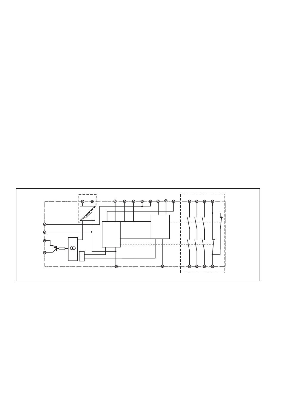
Fig. 1: Innenschaltbild/Internal Wiring Diagram/Schéma de principe