Pilz PNOZ X2.1C 24VAC/DC 2n/o User Manual
Page 4
- 4 -
- Zweikanalig: Öffnerkontakt von
Auslöseelement an S11-S12 und S21-
S22 anschließen.
•
Rückführkreis:
Externe Schütze in Reihe zu Startkreis
S33-S34 anschließen.
Die Sicherheitskontakte sind aktiviert (ge-
schlossen). Die Statusanzeigen für "CH.1",
"CH.2" leuchten. Das Gerät ist betriebs-
bereit.
Wird der Eingangskreis geöffnet, öffnen die
Sicherheitskontakte 13-14/23-24. Die
Statusanzeige erlischt.
Wieder aktivieren
• Eingangskreis schließen.
• Bei manuellem Start zusätzlich Taster
zwischen S33 und S34 betätigen.
Die Statusanzeigen leuchten wieder, die
Sicherheitskontakte sind geschlossen.
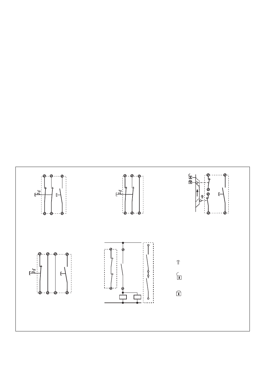
Anwendung
In Fig. 2 ... Fig. 6 sind Anschlussbeispiele
für Not-Halt-Beschaltung mit automati-
schem und manuellem Start, Schutztüran-
steuerungen sowie Kontaktvervielfachung
durch externe Schütze.
Beachten Sie bei Fig. 3: Das Gerät startet
bei Spannungsausfall und -wiederkehr
automatisch. Verhindern Sie einen uner-
warteten Wiederanlauf durch externe
Schaltungsmaßnahmen.
• Boucle de retour :
Câblage en série des contacts externes
dans le circuit de rèarmement S33-S34
Les contacts de sécurité se ferment. Les
LEDs "CH.1" et "CH.2" sont allumées.
L’appareil est prêt à fonctionner.
Si le circuit d’entrée est ouvert, les
contacts de sécurité 13-14/23-24
retombent. Les LEDs s’éteignent.
Remise en route :
• fermer le circuit d’entrée
• en cas de réarmement manuel, appuyer
sur le poussoir de validation entre S33-
S34.
Les affichages d'état s'allument à nouveau.
Les contacts de sécurité sont fermées.
Utilisation
Dans les figures 2 à 6 sont représentés
les différents cablages possibles :
poussoirs AU avec réarmement
automatique et surveillance du circuit de
réarmement, interrupteur de position et
augmentation du nombre des contacts par
contacteurs externes.
Dans le cas de la figure 3, l’appareil se
réarme automatiquement après une coupure
et une remise sous tension. Evitez tout
risque de redémarrage par un câblage
externe approprié.
• Feedback control loop:
Connect external contactors/relays in
series with reset circuit S33-S34.
The safety contacts are activated (closed).
The status indicators "CH.1" and "CH.2"
are illuminated. The unit is ready for
operation. If the input circuit is opened, the
safety contacts 13-14/23-24 open. The
status indicator goes out.
Reactivation
• Close the input circuit.
• For manual reset press the button
between S33-S34.
The status indicators light up again, the
safety contacts are closed.
Application
In Fig.2...Fig.6 are connection examples for
Emergency Stop wiring with automatic and
manual reset. Safety gate control as well as
contact expansion via external contactors.
Please note for Fig. 3: the device starts
automatically after loss of power. You
should prevent an unintended start-up by
using external circuitry measures.
S11
S12
S34
S22
S33
S21
S1
S3
S11
S12
S34
S22
S33
S21
S1
Fig. 3:
nur bei PNOZ X2.1C
: automat. Start/
Only PNOZ X2.1C
: automatic reset/
PNOZ X2.1C uniquement:
réarmement
automatique
S34
S33
S11
S22
S12
S21
S1
S3
S1
S2
13
14
K4
S33
S34
K4
K5
K5
K4
K5
Fig. 6: Anschlussbeispiel für externe
Schütze, einkanalig/Connection example for
external contactors/relays, single-channel/
Branchement contacteurs externes,
commande par 1 canal
betätigtes Element/Switch
activated/élément actionné
Tür nicht geschlossen/Gate
open/porte ouverte
Tür geschlossen/Gate closed/
porte fermée
S11
S12
S34
S22
S33
S21
UB
(L+)
A1
Fig. 4: Schutztürsteuerung zweikanalig,
manueller Start/Dual-channel safety gate
control, manual reset/Surveillance de
protecteur, commande par 2 canaux
Fig. 2: Eingangskreis zweikanalig, manuel-
ler Start/Two-channel input circuit, manual
reset/Commande par 2 canaux, réarmement
manuel
Fig. 5: Eingangskreis einkanalig, manueller
Start/Single-channel input circuit, manual
reset/Commande par 1 canal, réarmement
manuel