Pilz PSEN hs1.2p User Manual
Page 11
Dok.: 0800000639.doc / Stand : 4 / Ausgabedatum : 11.10.2010 / 2687-10
Blatt 11 von 16
Vorlage : 0850174292 Orig. 2
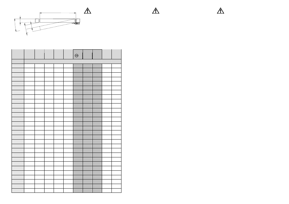
B
A
C
C1
α
Entscheidend für eine sicherheitsgerichtete
Applikation ist der Winkel, bei dem die
Zwangsöffnung erreicht wird!
Beim PSEN hs1 liegt der
Zwangstrennungswinkel bei 6° und kann sich
durch Toleranzen und Verschleiß um 2° bis auf
8° vergrößern. Zur Erleichterung bei der
Auswahl der entscheidenden Werte sind in der
Tabelle 1 diese Spalten hervorgehoben.
The decisive factor in safety applications is
the angle at which positive opening action is
achieved!
The positive opening angle of the PSEN hs1
hinge switch is 6° which can increase by 2°
to 8° due to tolerances and wear. To make
selection of the decisive values easier, these
columns are highlighted in Table 1.
L’angle auquel l'ouverture forcée est atteinte
est décisif pour une application orientée sur
la sécurité !
L’angle de séparation forcée est égal à 6°
dans le cas de la PSEN hs1. Des tolérances
et l’usure peuvent l’augmenter de 2°, il
atteint alors 8°. Ces colonnes sont mises en
évidence en gris foncé dans le tableau 1
pour faciliter le choix des valeurs décisives.
Tabelle1 / Table 1 / Tableau 1
6°
7°
8°
α
1°
2°
3°
4°
5°
9°
10°
B
C
100
1,7
3,5
5,2
7,0
8,7 10,5 12,2
13,9
15,6
17,4
150
2,6
5,2
7,9
10,5 13,1 15,7 18,3
20,9
23,5
26,0
200
3,5
7,0
10,5
14,0 17,4 20,9 24,4
27,8
31,3
34,7
250
4,4
8,7
13,1
17,4 21,8 26,1 30,5
34,8
39,1
43,4
300
5,2 10,5
15,7
20,9 26,1 31,4 36,6
41,8
46,9
52,1
350
6,1 12,2
18,3
24,4 30,5 36,6 42,7
48,7
54,8
60,8
400
7,0 14,0
20,9
27,9 34,9 41,8 48,7
55,7
62,6
69,5
450
7,9 15,7
23,6
31,4 39,2 47,0 54,8
62,6
70,4
78,1
500
8,7 17,4
26,2
34,9 43,6 52,3 60,9
69,6
78,2
86,8
550
9,6 19,2
28,8
38,4 47,9 57,5 67,0
76,5
86,0
95,5
600
10,5 20,9
31,4
41,9 52,3 62,7 73,1
83,5
93,9 104,2
650
11,3 22,7
34,0
45,3 56,7 67,9 79,2
90,5 101,7 112,9
700
12,2 24,4
36,6
48,8 61,0 73,2 85,3
97,4 109,5 121,6
750
13,1 26,2
39,3
52,3 65,4 78,4 91,4 104,4 117,3 130,2
800
14,0 27,9
41,9
55,8 69,7 83,6 97,5 111,3 125,1 138,9
850
14,8 29,7
44,5
59,3 74,1 88,8 103,6 118,3 133,0 147,6
900
15,7 31,4
47,1
62,8 78,4 94,1 109,7 125,3 140,8 156,3
950
16,6 33,2
49,7
66,3 82,8 99,3 115,8 132,2 148,6 165,0
1000
17,5 34,9
52,3
69,8 87,2 104,5 121,9 139,2 156,4 173,6
1050
18,3 36,6
55,0
73,2 91,5 109,8 128,0 146,1 164,3 182,3
1100
19,2 38,4
57,6
76,7 95,9 115,0 134,1 153,1 172,1 191,0
1150
20,1 40,1
60,2
80,2 100,2 120,2 140,1 160,0 179,9 199,7
1200
20,9 41,9
62,8
83,7 104,6 125,4 146,2 167,0 187,7 208,4
1250
21,8 43,6
65,4
87,2 108,9 130,7 152,3 174,0 195,5 217,1
1300
22,7 45,4
68,0
90,7 113,3 135,9 158,4 180,9 203,4 225,7
1350
23,6 47,1
70,7
94,2 117,7 141,1 164,5 187,9 211,2 234,4
1400
24,4 48,9
73,3
97,7 122,0 146,3 170,6 194,8 219,0 243,1
1450
25,3 50,6
75,9 101,1 126,4 151,6 176,7 201,8 226,8 251,8
1500
26,2 52,3
78,5 104,6 130,7 156,8 182,8 208,8 234,7 260,5
Berechnungsbeispiel
Der tatsächliche vorhandene
Türspalt C1 kann nach Ermittlung
des Wertes C nach
nebenstehender Tabelle 1,
abzüglich der Rahmenbreite, leicht
berechnet werden.
C1 = C – A
Beispiel:
Eine Tür aus A= 40 mm
Aluminiumprofil mit einer Breite B
von 900 mm soll durch den Einsatz
des PSEN hs1 abgesichert
werden.
Der Schaltpunkt wird bei
geschlossener Tür fixiert, der
PSEN hs1 typische Schaltpunkt
liegt nun in Öffnungsrichtung bei
α= 3°. Aus der nebenstehenden
Tabelle ergibt sich dafür im
Neuzustand ein Türspalt C von ca.
47,1 mm.
Der tatsächliche Türspalt, kann
nach der Formel C1=C-A
berechnet werden.
C1= 47,1 mm – 40 mm = 7,1 mm
α = Öffnungswinkel der Tür
B
= Türbreite in mm
C
= Türspalt in mm bei der
Rahmenbreite A = 0 mm
Calculation example
The actual gate gap C1 can be
easily calculated after determining
the value C from Table 1 opposite
minus the frame width.
C1 = C – A
Example:
A safety gate made from
A= 40 mm aluminium section with
a width B of 900 mm is to be
secured by the PSEN hs1 hinge
switch.
The switching point is determined
with the safety gate closed, the
typical switching point of the PSEN
hs1 is α= 3° in opening direction.
The table opposite shows a gate
gap C of approx. 47.1 mm when
new.
The actual gate gap can be
calculated using the formula C1=C-
A.
C1 = 47.1 mm – 40 mm = 7.1 mm
α
= Opening angle of gate
B
= Gate width in mm
C
= Gate gap in mm at
frame width A = 0 mm
Exemple de calcul
Il est possible de calculer
facilement le jeu entre dormant et
vantail vraiment disponible C1 en
calculant la valeur C en fonction du
tableau 1 ci-contre, moins la
largeur du dormant.
C1 = C – A
Exemple :
Il faut protéger une
porte en profil d’aluminium A = 40
mm de 900 mm de largeur (B)
avec la PSEN hs1.
Le point de commutation est
déterminé lorsque la porte est
fermée, le point de commutation
typique de la PSEN hs1 est alors
égal à α= 3° dans le sens de
l’ouverture. Il ressort du tableau ci-
contre que le jeu entre dormant et
vantail C est égal à environ 47,1
mm à l’état neuf.
Il est possible de calculer le jeu
réel entre dormant et vantail avec
la formule C1 = C-A.
C1= 47,1 mm – 40 mm = 7,1 mm
α
= Angle d'ouverture de la porte
B
= Largeur de la porte en mm
C
= Jeu en millimètres pour
un dormant dont la largeur
A = 0 mm