Ssi communication mode, English, Installation / preparation for commissioning – Pilz PSEN enc s2 eCAM User Manual
Page 25: 2 ssi communication mode
Installation / Preparation for commissioning
Pilz GmbH & Co. KG, Felix-Wankel-Straße 2, 73760 Ostfildern, Deutschland
Telefon +49 711 3409-0, Telefax +49 711 3409-133, E-Mail: [email protected]
23
English
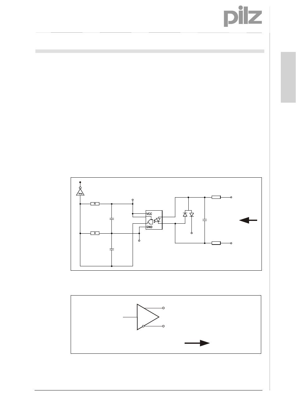
5.2 SSI communication mode
SSI mode is a synchronous serial communication mode for the position of the
measuring system. By using the RS422 interface for communication, sufficiently high
transmission rates can be achieved.
The measuring system receives a sequence of clock signals from the data receiver
(control system) and responds with the current position value, which is transmitted
serially and synchronously with the sent clock pulse.
As data transfer is synchronised by the start of the clock signals, it is not necessary to
use single-step codes such as Gray code, for example.
The data signals Data+ and Data– are sent using cable transmitters (RS422). The
clock signals Clock+ and Clock- are received via optocouplers to protect against
damage resulting from interference, potential differences or reverse polarity.
SSI-Clock+
SSI-Clock-
65
Ω
65
Ω
2.2 nF
N.C.
GND
+5V
C
C
BAV99
Opto-Koppler
Fig. 8: SSI principle input circuit (Key: Opto-Koppler – Optocoupler)
Data+
Data-
RS422
Fig. 9: SSI output circuit