Noise gate, Insert – Allen&Heath GLD-112 Reference Guide User Manual
Page 10
GLD Touch Screen Reference V1.4 – Issue 1 10
ALLEN
&
HEATH
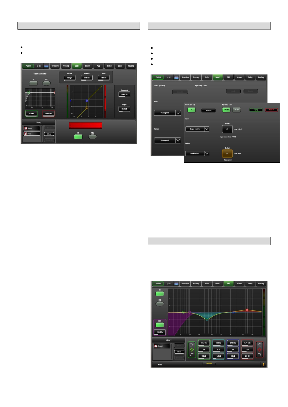
3.9 Noise Gate page
The Noise Gate automatically attenuates the signal when it
drops below its threshold level. For example to:
Reduce excessive ring on a kick or tom drum
Reduce hiss on a noisy keyboard when not played.
Touch and drag the curve or touch a parameter box. It
highlights orange to show its value can be adjusted using
the screen Rotary.
Depth - Sets how much the signal is attenuated when the
gate closes. A good starting point is around 30dB. Reduce
for less attenuation. If Depth is set to 0dB the gate will not
attenuate the signal.
Threshold - Sets the level at which the gate opens to let the
signal be heard. The meter on the left lines up with the
graph and shows the signal at the input to the gate. The
gain reduction meter on the right shows when the gate is
closed. The histogram below shows gate activity over time.
Attack, Hold, Release - These controls set how fast the
gate opens when the signal rises above the threshold, how
long it is held open after the signal falls below the threshold
and how long it takes to attenuate after it closes.
Side Chain Filter - Sets the frequency range of the signal
that triggers the gate. Use this to prevent false triggering of
the gate by filtering out low or high frequencies outside the
fundamental range of the instrument being gated. For
example, the low frequencies of a kick drum causing the
gate on a rack tom to open.
In - Switch the gate in or out of circuit. The side chain can
also be switched in or out of the gate. The curve turns
yellow and the gain reduction meter displays red when the
gate is switched in.
Library - You can store and name the current gate settings
as a preset in the Library. Existing presets can be
overwritten with the current settings. User Libraries can be
exported and imported via USB key. To do this go to the
Setup / Memory / Library Manager
screen.
Sel buttons – Touch while holding the Copy, Paste or
Reset key to copy the gate settings to other channels or to
reset them to default.
3.10 Insert page
You can insert external equipment or one of the 8 internal
FX units into a channel or mix signal path:
An external signal processor using physical sockets
One of the 8 internal Rack FX
Computer plug-ins via the I/O Port
Networked audio via the I/O Port
Use the drop-down menus to assign the Insert Send and
Return to physical sockets, the I/O Port or an FX unit.
Touch
Apply.
In button – Becomes available once the insert is assigned.
Switch the inserted device in or out of circuit.
+4dBu/-10dBV – Choose the operating level of the insert
point. +4dBu (default) is the typical setting for professional
audio equipment. -10dBV (-8dBu) is a standard for lower
level consumer equipment.
3.11 PEQ page
The Parametric Equaliser (PEQ) provides 4 fully adjustable
bands of equalisation allowing very precise tone control. It
can be adjusted using dedicated rotary controls on the
surface or using the touch screen. For screen control, touch
and drag the curve or touch a parameter box and use the
Rotary.