Rice Lake SCT-10 User Manual
Page 40
36 SCT Weight Transmitter Operator’s Manual
N° BYTES: Number of bytes transmitted as a value of the registers (2
bytes per register)
VAL. REG.: Contents of the register beginning from the first.
The answer contains the register identification modified after the command has
been executed.
Communication Error Management
The communication strings are controlled by CRC (Cyclical Redundancy
Check).
In case of a communication error the slave will not respond with any string. The
master must allow for a time-out before response reception. If no response is
received it infers that a communication error has occurred.
In the event of a string received correctly but not executable, the slave responds
with an EXCEPTIONAL RESPONSE. The "FUNCTION" field is transmitted
with the MSB at 1.
List Of Usable Registers
The MODBUS-RTU protocol implemented on this instrument can manage a
maximum of 32 registers read and written in a single query or response.
R
= the register can be read only
W
= the register can be written only
R/W = the register can be both read and written
H
= high half of the DOUBLE WORD forming the number
L
= low half of the DOUBLE WORD forming the number
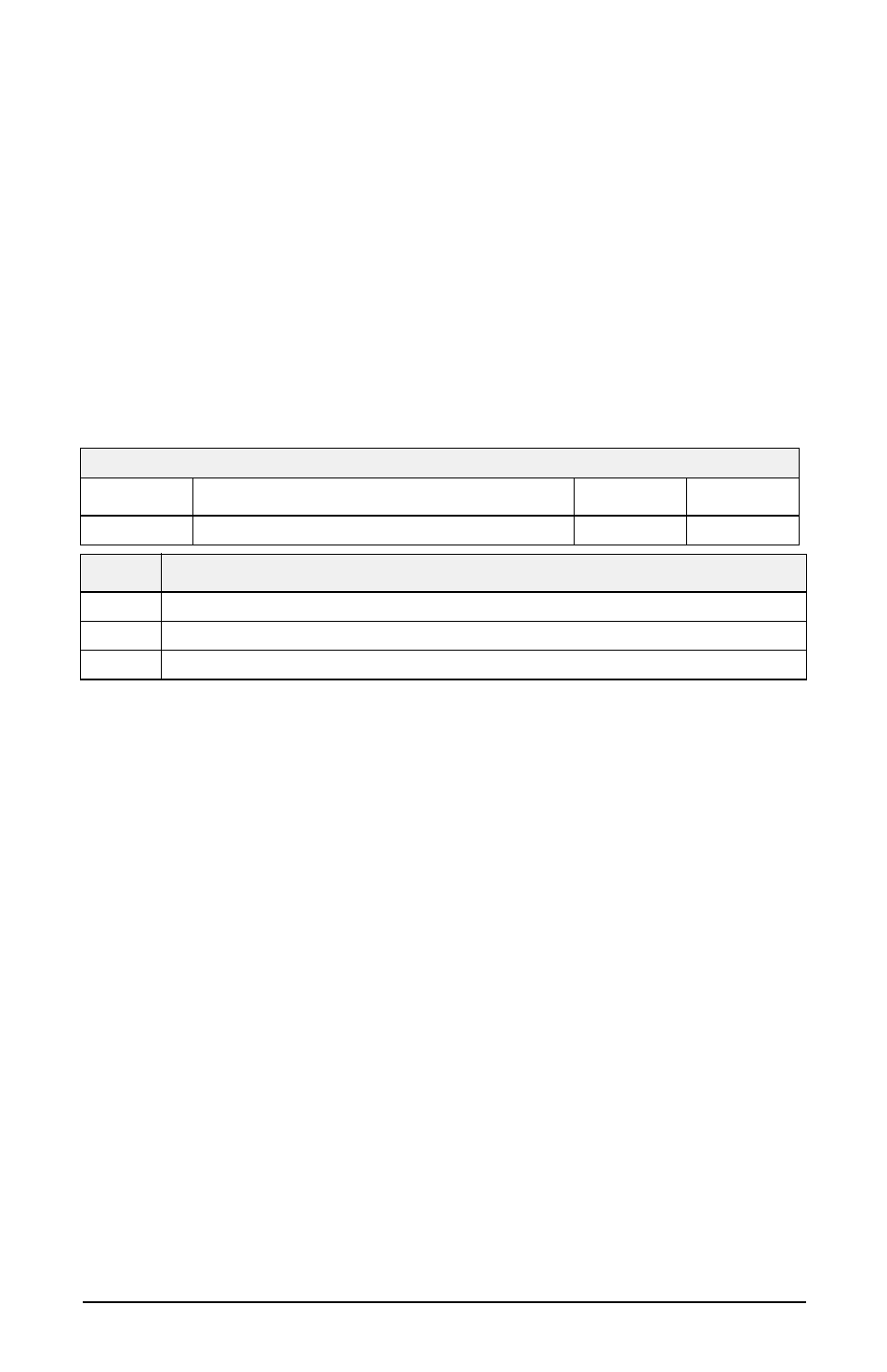
EXCEPTIONAL RESPONSE
Address
Function
Code
2 bytes
A
Funct + 80h
CRC
CODE
DESCRIPTION
1
ILLEGAL FUNCTION (Function not valid or not supported)
2
ILLEGAL DATA ADDRESS (The specified data address is not available)
3
ILLEGAL DATA VALUE (The data received have no valid value)
- 1010 Potted & Unpotted Single Point, Aluminum (58 pages)
- 120 Digital Weight Indicator (44 pages)
- 120 Plus Digital Weight Indicator (56 pages)
- 320IS Intrinsically-Safe Digital Weight Indicator - Installation Manual (76 pages)
- 320IS Intrinsically-Safe Digital Weight Indicator - Timer Relay Instruction Sheet (2 pages)
- 320IS Intrinsically-Safe Digital Weight Indicator - Battery Charging Instruction Sheet (2 pages)
- 320IS Intrinsically-Safe Digital Weight Indicator - I/O Module for Intrinsically Safe Systems Installation Manual (15 pages)
- 320IS Intrinsically-Safe Digital Weight Indicator - IS-6V Battery Pack Instruction Sheet (6 pages)
- 320IS Intrinsically-Safe Digital Weight Indicator - IS-EPS-100-240 Power Supply Instructions (6 pages)
- 320IS Plus Intrinsically Safe Digital Weight Indicator - Installation Manual (90 pages)
- 420 Plus HMI Digital Weight Indicator Installation Manual (60 pages)
- 420 Plus HMI Digital Weight Indicator Operator Card (3 pages)
- 420 Plus Digital Weight Indicator - 7.5V DC-to-DC Power Supply Installation (4 pages)
- 420 Plus Digital Weight Indicator - IQ plus 355 - 390-DC - 590-DC & 420 Plus Quick Connector Cable Installation Instructions (1 page)
- 480 Legend Series Digital Weight Indicator Installation Manual (68 pages)
- 480 Legend Series Digital Weight Indicator Operator Card (1 page)
- 480 Panel Mount Option (4 pages)
- 520 Analog Output Card Installation (2 pages)
- 520 Digital Weight Indicator Operator Card (4 pages)
- 520 HMI Digital Weight Indicator Installation Manual (98 pages)
- 520 HMI Digital Weight Indicator Manual - BCD Option (18 pages)
- 520 Configurable Weight Indicator - Remote I/O Indicator Interface Installation and Programming Manual (31 pages)
- 520 Configurable Weight Indicator - ControlNet Interface Installation and Programming Manual (23 pages)
- 520 Configurable Weight Indicator - DeviceNet Interface Installation and Programming Manual (21 pages)
- 520 Configurable Weight Indicator - Ethernet Interface Installation and Configuration Manual (38 pages)
- 520 Configurable Weight Indicator - EtherNet/IP Interfac Installation and Programming Manual (26 pages)
- 520 Configurable Weight Indicator - Profibus DP Interface Installation and Programming Manual (21 pages)
- 550-10-1 Digital Chair Scale - Operation Manual (26 pages)
- 550-10-1 Digital Chair Scale - Technical Manual (34 pages)
- 590-AG Livestock Digital Weight Indicator (56 pages)
- 65059 Mild Steel 3-Module Kit - RL50210 Load Cell Mounting Kit Installation Guide (13 pages)
- 720i Programmable Indicator/Controller - 6V DC-to-DC Power Supply Installation Instructions (4 pages)
- 720i Programmable Indicator/Controller - Installation Manual (122 pages)
- 720i Programmable Indicator/Controller - Operator Card (4 pages)
- 720i Programmable Indicator/Controller - Analog Output Card Installation Instructions (4 pages)
- 720i Programmable Indicator/Controller - CW-90/90X - iQUBE2 - LaserLT WLAN Installation Instructions (12 pages)
- 720i Programmable Indicator/Controller - USB Interface Card Installation Instructions (2 pages)
- 820i Programmable Indicator/Controller - Installation Manual (112 pages)
- 820i Programmable Indicator/Controller - Panel Mount Enclosure Installation Instructions (6 pages)
- 880 Performance Series Indicator/Controller Operators Manual (36 pages)
- 880 Performance Series Indicator/Controller Technical/Service Manual (120 pages)
- 880 Performance Series Panel Mount Indicator/Controller - Adapter Panel Installation (4 pages)
- 880 Performance Series Panel Mount Indicator/Controller - Analog Output Card Option Installation Manual (6 pages)
- 880 Performance Series Panel Mount Indicator/Controller - DeviceNet Interface Option Installation and Programming Manual (28 pages)
- 880 Performance Series Panel Mount Indicator/Controller - EtherNet/IP Interface Option Installation and Programming Manual (32 pages)