4 analog output – Rice Lake SCT-10 User Manual
Page 25
Configuration 21
2.4
Analog Output
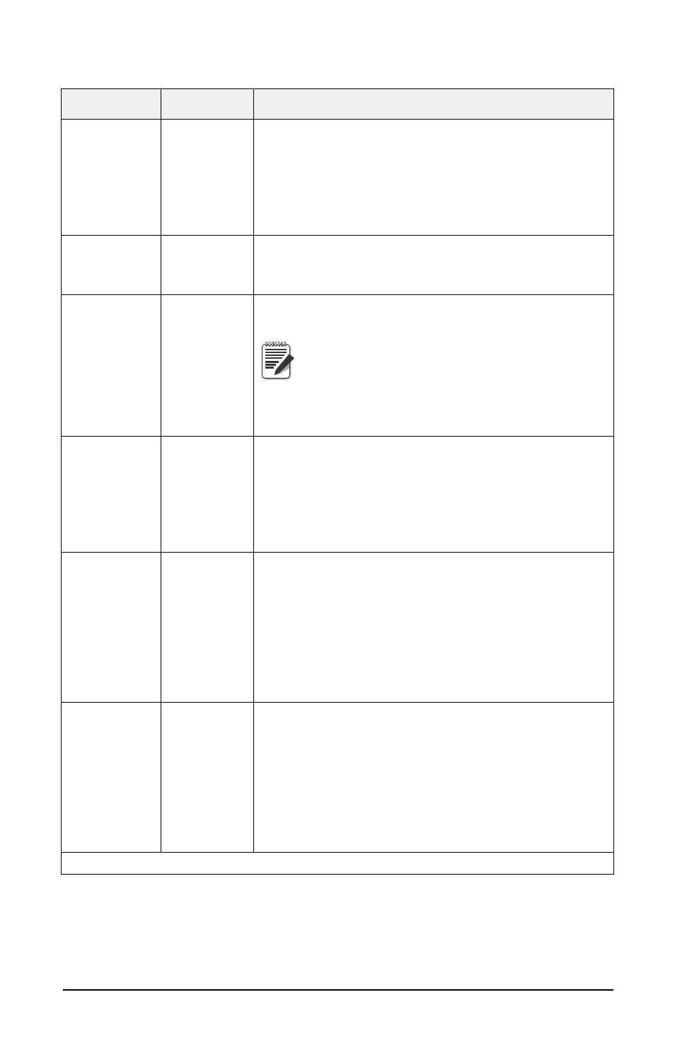
Parameter
Choices
Description
tYPE
4-20 mA *
0-20 mA
0-10 V
0-5 V
-10 +10 V
-5 +5 V
Selects the analog output type.
See “Soldered Jumper” on page 22
See “Soldered Jumper” on page 22
NodE
Enter #
Gross
Net
Select mode to be tracked, gross or net. If the net
function is not active, the analog output varies
according to gross weight.
ANA 0
Enter #
Set the weight value for the minimum analog output
value.
Only set a value different from zero to
limit the analog output range.
E.G.:: for a full scale value of 10000 kg, a 4 mA
signal at 5000 kg is required, and 20 mA at 10000
kg, in this case, instead of zero, set 5000 kg.
ANA FS
Enter #
Set the weight value for the maximum analog output
value; it must correspond to the value set in the PLC
program (default: calibration full scale).
E.g.: if using a 4-20 mA output and in the PLC
program a 20 mA = 8000 kg is desired, set the
parameter to 8000.
COr 0
Analog output correction to zero: if necessary adjust
the analog output, allowing the PLC to indicate 0.
The sign ‘-‘ can be set for the last digit on the left.
E.g.: For a 4-20 mA output and a minimum
analog setting, the PLC or tester reads 4.1 mA.
Set the parameter to 3.9 to obtain 4.0 on the PLC
or tester. (See “Analog Output Type Scale
Corrections” on page 22)
COr FS
Full scale analog output correction: if necessary
adjust the analog output, allowing the PLC to
indicate the value set in the AnA FS parameter.
E.g. For a 4-20 mA output with the analog set to
full scale and the PLC or tester reads 19.9 mA,
set the parameter to 20.1 to obtain 20.0 on the
PLC or tester. (See “Analog Output Type Scale
Corrections” on page 22)
*
- indicates default value.
Table 2-6. Analog Output Menu
Note