8 setpoints programming – Rice Lake SCT-10 User Manual
Page 33
Configuration 29
2.8
Setpoints Programming
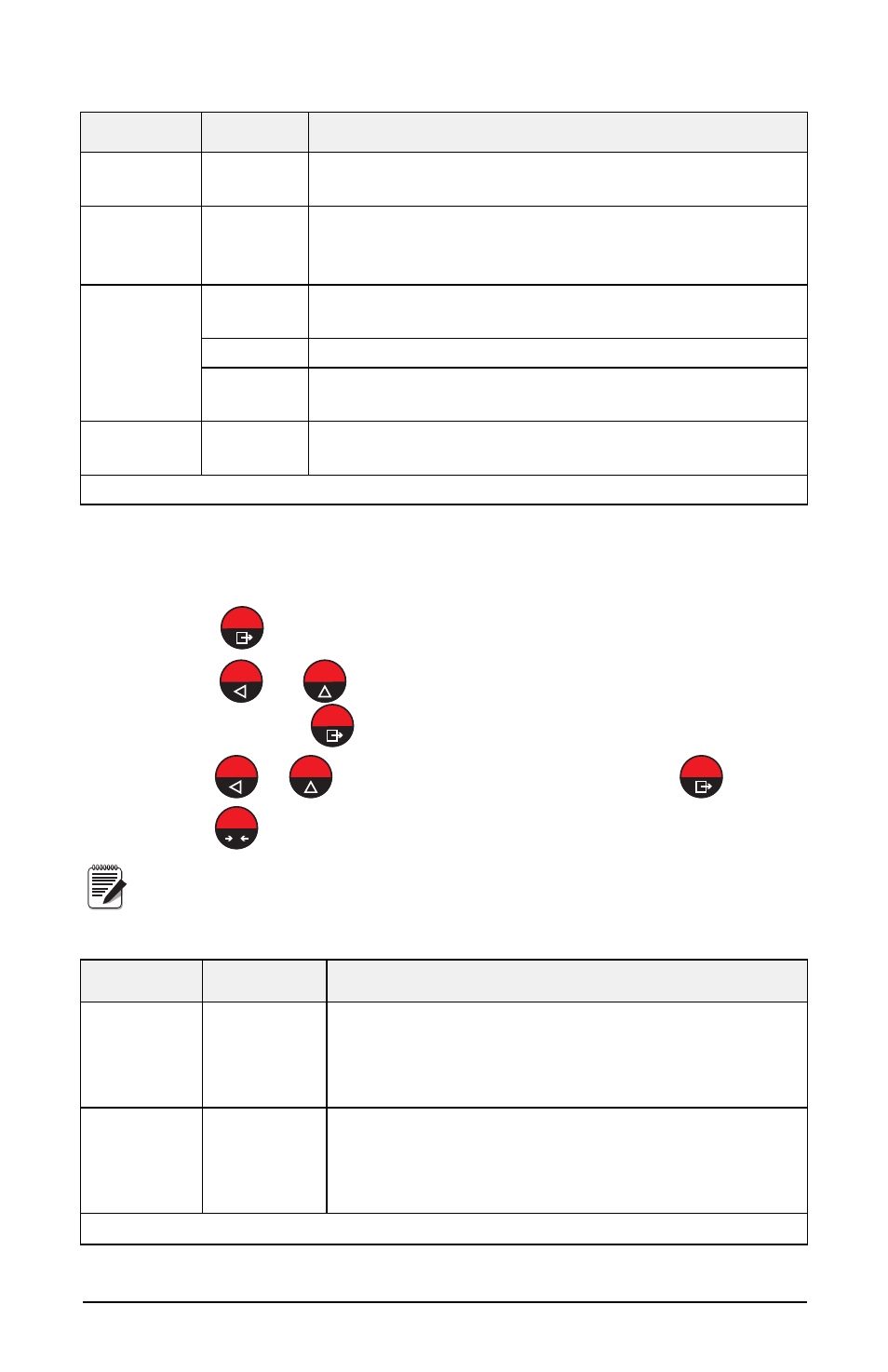
1. Press
to enter setpoints and hysteresis settings.
2. Press
or
until desired setpoint or hysteresis parameter is
displayed, press
.
3. Press
or
until desired value is displayed, press
.
4. Press
to exit setpoints and hysteresis settings.
These values are set to zero if the calibration is changed
significantly (see Section 2.1.1 “Theoretical Calibration” on
page 14 and Section 2.1.5 “Weight (Span) Calibration (With Test
Weights)” on page 16).
Parameter Choices
Description
In
N/A
Input Test - for each open input 0 is displayed, 1 is
displayed when the input is closed.
Out
0 *
1
Output Test -
Setting 0 - the corresponding output opens.
Setting 1 - the corresponding output closes.
ANALOG ANALOG
Allows the analog signal to range between the minimum
and the maximum values starting from the minimum.
NA
current output test
UOLt1
voltage output test
NU-CEL
N/A
Millivolt Test - displays the load cell response signal in
mV with four decimals.
*
- indicates default value.
Table 2-9. Test Menu
Parameter
Choices
Description
SEtP 1
SEtP 2
0-Full Scale
0 *
Setpoint; relay switching occurs when the weight
exceed the value set in this parameter. The type of
switching is settable (see “Outputs And Inputs
Configuration” on page 26).
HYStE 1
HYStE 2
0-Full Scale
0 *
Hysteresis, value to be subtracted from the setpoint to
obtain contact switching for decreasing weight. For
example with a setpoint at 100 and hysteresis at 10,
the switching occurs at 90 for decreasing weight.
*
- indicates default value.
Table 2-10. Setpoints
MENU
TARE
MENU
TARE
MENU
0
ESC
Note