4 electrical connections, 6sct weight transmitter operator’s manual – Rice Lake SCT-10 User Manual
Page 10
6
SCT Weight Transmitter Operator’s Manual
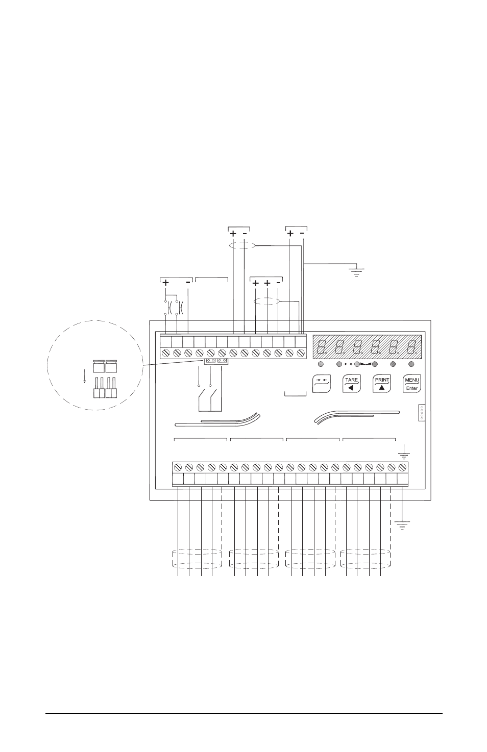
1.4
Electrical Connections
• It is recommended that the negative side of the power supply be grounded.
• It is possible to power up to eight 350 ohm load cells or sixteen 700 ohm
load cells.
• Connect terminal “0 VDC” to the RS-485 common of the connected
instruments in the event that these receive alternating current input or that
they have an opto-isolated RS-485.
• In case of an RS-485 network with several devices it is recommended to
activate the 120 ohm termination resistance on the two devices located at the
ends of the network, see Section 2.5.1 “RS-485 Serial Communication” on
2 outputs: configurable setpoints or remote output management via protocol.
2 inputs (Default: SEMI-AUTOMATIC ZERO input 1; NET/GROSS input
2): settable to have the following functions: SEMI-AUTOMATIC ZERO,
NET/GROSS, PEAK, or REMOTE CONTROL (see Section 2.6 “Outputs
And Inputs Configuration” on page 26).
13
1 2 3 4 5 6 7 8 9
1112
10
21
14 1516 1718 19 20
SH
LOAD CELLS IN PARALLEL
IN1
IN2
IN COM
OU
T1
OU
T2
+ RS
485
-
RS485
mA
V
mA-V COM
NET
0
kg
g
L
INPUTS
5-24Vdc
OUTPUTS
24Vdc
60mA
RS485
OUTPUT
12-24Vdc
ANALOG
RS485 termination
0
ESC
33
31
30
32
28
27
25
2324
26
29
22
34
+ 12-24
0 VDC
POWER
+ EX
-
EX
-
SIG
+ SI
G
-
EX
+ EX
-
SIG
+ SI
G
SH
-
EX
+ EX
-
SIG
+ SI
G
SH
-
EX
+ EX
-
SIG
+ SIG
SH
J1
J2
SCT
Current output: max load 300 Ohm
Voltage output: min. load 10 kOhm
- EXCITA
TION
+ EXCITATION
- SIG
NAL
+ SIGNA
L
- EXCITA
TION
+ EXCITATION
- SIGNAL
+ SIGNA
L
- EXCITA
TION
+ EXCITATION
- SIGNAL
+ SIGNA
L
- EXCITA
TION
+ EXCITATION
- SIGNAL
+ SIGNA
L