1 parameters, Parameters – Rice Lake MSI-8000 RF Remote Display - ScaleCore Configuration Management Program (ScCMP) User Manual
Page 27
Advanced Configuration
23
6.3.1
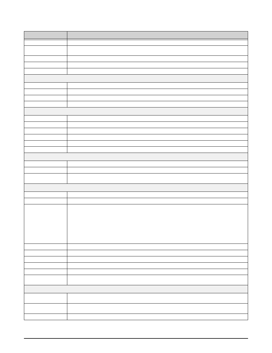
Parameters
Parameter
Description
ID
Sensor index. Typical range 0 to 4 for load and math sensors.
Enabled
Enable or Disable the sensor. Disabling an unused sensor will improve performance of other enabled
sensors.
Type
Sensor type (Loadcell or Math).
Name
Name of this sensor. Maximum number of characters is 20.
SWFilter
The software filter level for the sensor. Typical range 0-3 where the lower number is less filtering.
Display
Capacity
The display capacity (less than or equal to the calibration capacity).
Countby
The display countby (greater than or equal to the calibration countby).
Units
The display unit of measure.
Percent Underload
The percentage of under load readings before giving an under load error.
Zero
Zero Band Hi
Zero high band in terms of percentage of capacity, range 1 to 100.
Zero Band Lo
Zero low band in terms of percentage of capacity, range 1 to 20.
AZM Range
AZM range in d.
AZM Period
AZM period in ticks (each tick is 50 milliseconds).
Power Up Zero Hi
Power up Zero high band in term of percentage of capacity, range 1 to 25.
Power Up Zero Lo
Power up Zero low band in term of percentage of capacity, range 1 to 20.
Motion
Motion Period
Motion window period in ticks (each tick is 50 milliseconds).
Motion Band
Motion detection band in d of a load cell, range 0 to 255, 0==1/2 d, 1==1d and so on.
Motion Pending Time
Motion pending time in ticks (each tick is 50 milliseconds). The time required to wait for a stable load
before zero, tare or total actions can be performed.
Tare/Total
LC Mode
Net/Gross
Tare Auto Clear
Sets the Tare Auto Clear function to Disabled, Enabled, or On Total.
Total Mode
Load cell total mode.
• Disabled
• Auto Load
• Auto Norm
• Auto Peak
• Load Drop
• On Accept
• On Command (manual)
Drop Threshold
Threshold in percentage of capacity to drop below before totaling be allowed.
Rise Threshold
Threshold in percentage of capacity to rise above before totaling be allowed.
Minimum Stable Time
Minimum stable time before it can be total.
Total On Accept Upper
Upper bound weight of on accept total mode.
Total On Accept Lower
Lower bound weight of on accept total mode.
Capacity Conversion
Selects between true and half capacity conversion. Example: 1000 lb scale true conversion is 454 kg
where half conversion is 500 kg.
Peak/Lift
Lift Threshold
Configurable upper threshold for the lift counter. Lift threshold as percentage of capacity. 0==0.5%, 1 to
100 means 1 to 100%. Above this threshold is a lift event.
Drop Threshold
Configurable lower threshold for the lift counter. Drop threshold as percentage of capacity. 0==0.5%, 1
to 100 means 1 to 100%. Below this threshold is a drop event.
Sample Speed
Sensor sampling speed for all sensor in peak hold mode.
Table 6-3. Load Cell and Math Sensor Parameters
- MSI-7300 Dyna-Link 2 - ScaleCore Configuration Management Program (ScCMP) MSI-4260 Port-A-Weigh - ScaleCore Configuration Management Program (ScCMP) MSI-3460 Challenger 3 - ScaleCore Configuration Management Program (ScCMP) MSI Tension Dynamometers - ScaleCore Configuration Management Program (ScCMP) MSI Indicators/Remote Displays - ScaleCore Configuration Management Program (ScCMP) MSI Crane Scales - ScaleCore Configuration Management Program (ScCMP) Crane Scales - ScaleCore Configuration Management Program (ScCMP)