3 power pins, 4 power front panel header, Jrex plus lx user's guide – Kontron JRexplus-LX User Manual
Page 37: 1 power led
KTD-S0001-C
Page 33
Power Supply
JRexplus LX User's Guide
+5V
470R
C
o
nn
e
c
to
r
+
-
Power LED
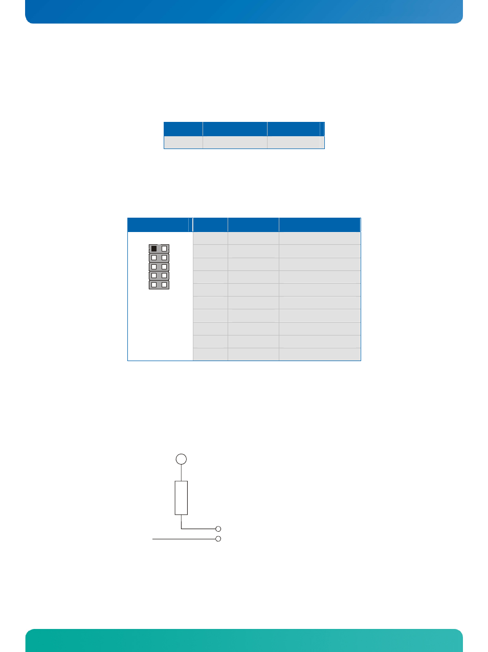
18.3 Power Pins
Every power pin on the power connector supplement is limited to a maximum current and the following
limitations apply:
Power
Number of Pins
Max. Current
5VSB
1
1A
18.4 Power Front Panel Header
The power button and other power signals are available through the pin strip FP2 (10 pins).
Header
Pin
Signal Name
Function
1
PWR_LED+
Power LED (positive)
2
PWR_BTN+
Power button (positive)
3
N.C.
Not connected
4
PWR_BTN-
Power button (negative)
5
PWR_LED-
Power LED (negative)
6
N.C.
Not connected
7
RSVD
Reserved
8
RSVD
Reserved
9
GND
Ground
1
2
9
10
10
RSVD
Reserved
18.4.1 Power
LED
The following picture illustrates the onboard wiring.
- CP3003-SA uEFI BIOS (72 pages)
- CP3003-SA (36 pages)
- CP3002 (38 pages)
- CP3002-RC uEFI (64 pages)
- CP-RIO3-05 (42 pages)
- CP3002-RC (30 pages)
- CP342 (52 pages)
- CP930 (46 pages)
- CP932 (52 pages)
- CP346 (72 pages)
- CP384 (66 pages)
- CP383 (74 pages)
- CP382 (58 pages)
- CP381 (60 pages)
- CP372 (64 pages)
- CP371 (60 pages)
- CP-RIO3-04S (38 pages)
- CP390 (36 pages)
- CPS3410 (9 pages)
- CPS3402 (9 pages)
- CPS3105 (9 pages)
- CPS3101 (9 pages)
- CPS3003-SA (19 pages)
- PB-SIO4 (34 pages)
- PB-SIO4A (34 pages)
- PB-DOUT8 (34 pages)
- VMOD-2 (82 pages)
- VSBC-32 (110 pages)
- VM42 (62 pages)
- Bootstrap Loader (24 pages)
- VMP1 with Netbootloader (120 pages)
- VMP1 (106 pages)
- NetBootLoader (86 pages)
- VMP2 (142 pages)
- VMP3 (154 pages)
- CP-RIO6-923 (32 pages)
- CP-RIO6-923-F (32 pages)
- CP-RIO6-001 (28 pages)
- CP-RIO6-001-HD-VGA (46 pages)
- CP-RIO6-M (20 pages)
- CP-RIO6-B (28 pages)
- CP6925 (42 pages)
- CP6002 uEFI BIOS (76 pages)
- CP6002 IPMI (40 pages)
- CP6002 (42 pages)