Jrex plus lx user's guide – Kontron JRexplus-LX User Manual
Page 23
KTD-S0001-C
Page 19
Serial Port Interfaces
JRexplus LX User's Guide
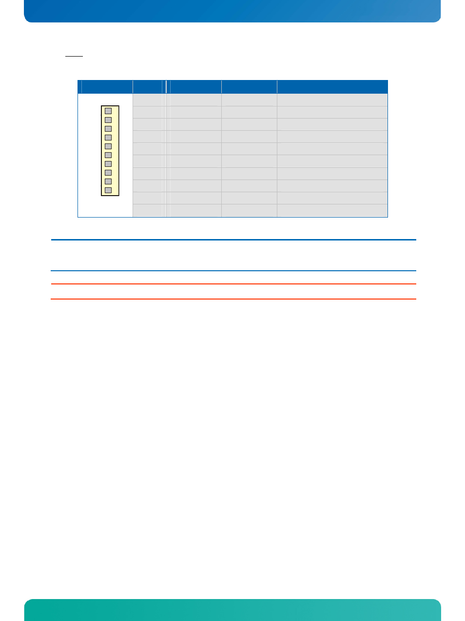
The same connector X10 can be used as a RS-422 or RS-485 interface. The configuration is changeable in
the BIOS Setup.
Header
Pin
Signal RS-422
Signal RS-485
Function
1
TX-
TX- / RX-
Transmit data - / Receive data -
2
N.C.
N.C.
Not connected
3
RX+
N.C.
Receive data + / Not connected
4
N.C.
N.C.
Not connected
5
TX+
TX+ / RX+
Transmit data + / Receive data +
6
N.C.
N.C.
Not connected
7
RX-
N.C.
Receive data - / Not connected
8
N.C.
N.C.
Not connected
9
GND
GND
Ground
1
10
VCC
1)
VCC
1)
Power +5V
Note:
1)
To protect the external power lines of peripheral devices make sure that
- the wires have the right diameter to withstand the maximum available current.
- to enclosure of the peripheral device fulfills the fire-protecting conditions of IEC/EN 60950.
Attention: A RS-422/RS-485 terminating resistor is not equipped on the JRexplus LX.
- CP3003-SA uEFI BIOS (72 pages)
- CP3003-SA (36 pages)
- CP3002 (38 pages)
- CP3002-RC uEFI (64 pages)
- CP-RIO3-05 (42 pages)
- CP3002-RC (30 pages)
- CP342 (52 pages)
- CP930 (46 pages)
- CP932 (52 pages)
- CP346 (72 pages)
- CP384 (66 pages)
- CP383 (74 pages)
- CP382 (58 pages)
- CP381 (60 pages)
- CP372 (64 pages)
- CP371 (60 pages)
- CP-RIO3-04S (38 pages)
- CP390 (36 pages)
- CPS3410 (9 pages)
- CPS3402 (9 pages)
- CPS3105 (9 pages)
- CPS3101 (9 pages)
- CPS3003-SA (19 pages)
- PB-SIO4 (34 pages)
- PB-SIO4A (34 pages)
- PB-DOUT8 (34 pages)
- VMOD-2 (82 pages)
- VSBC-32 (110 pages)
- VM42 (62 pages)
- Bootstrap Loader (24 pages)
- VMP1 with Netbootloader (120 pages)
- VMP1 (106 pages)
- NetBootLoader (86 pages)
- VMP2 (142 pages)
- VMP3 (154 pages)
- CP-RIO6-923 (32 pages)
- CP-RIO6-923-F (32 pages)
- CP-RIO6-001 (28 pages)
- CP-RIO6-001-HD-VGA (46 pages)
- CP-RIO6-M (20 pages)
- CP-RIO6-B (28 pages)
- CP6925 (42 pages)
- CP6002 uEFI BIOS (76 pages)
- CP6002 IPMI (40 pages)
- CP6002 (42 pages)