Kontron JRexplus-LX User Manual
Page 18
KTD-S0001-C Page
14
Graphics
Interface
JRexplus LX User's Guide
7.2.2
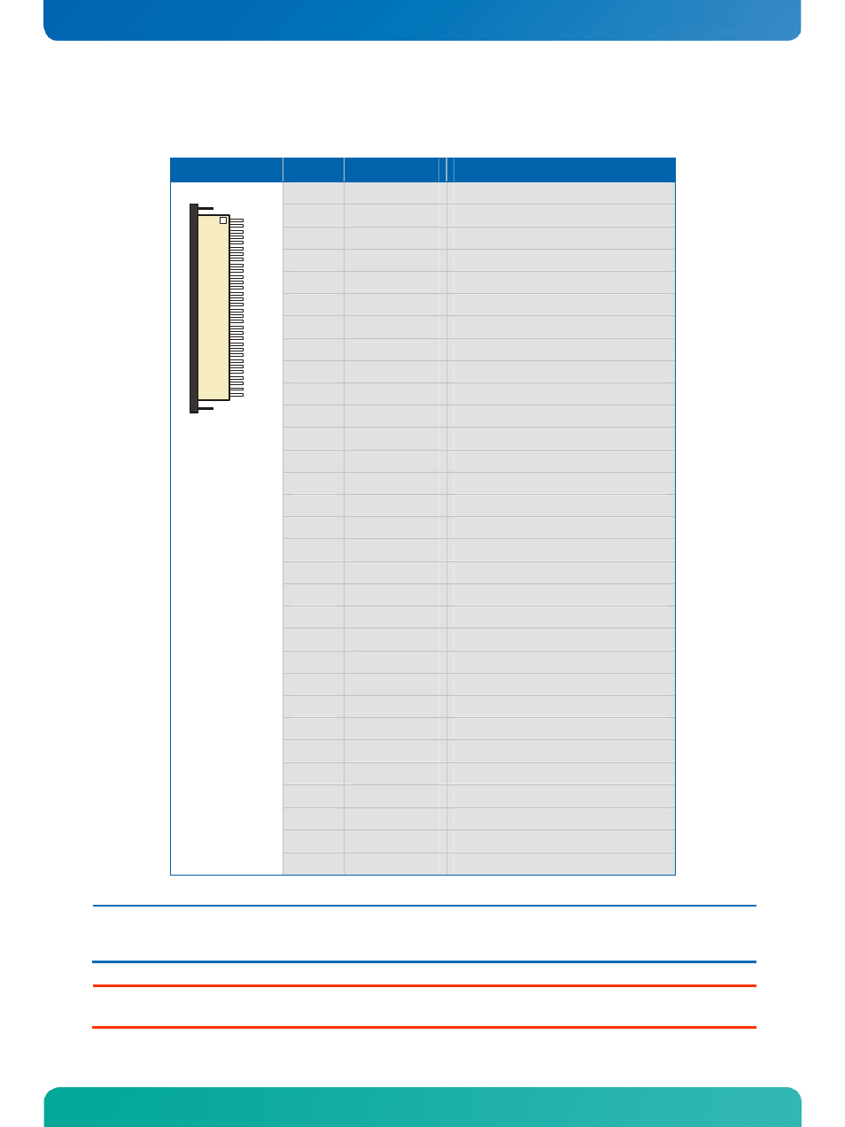
18 Bit Digital Connector
Header
Pin
Signal Name
Function
1
GND
Ground
2
PCLK
Data shift clock
3
PHS
Horizontal sync
4
PVS
Vertical sync
5
GND
Ground
6
PR0
Red color data line 0
7
PR1
Red color data line 1
8
PR2
Red color data line 2
9
PR3
Red color data line 3
10
PR4
Red color data line 4
11
PR5
Red color data line 5
12
GND
Ground
13
PG0
Green color data line 0
14
PG1
Green color data line 1
15
PG2
Green color data line 2
16
PG3
Green color data line 3
17
PG4
Green color data line 4
18
PG5
Green color data line 5
19
GND
Ground
20
PB0
Blue color data line 0
21
PB1
Blue color data line 1
22
PB2
Blue color data line 2
23
PB3
Blue color data line 3
24
PB4
Blue color data line 4
25
PB5
Blue color data line 5
26
GND
Ground
27
PDE
Data enable
28 - 29
VCC
1)
Power +3.3V or +5V
30
R/L
Rotate image left or right (option)
31
U/D
Rotate image up or down (option)
1
32
32
RSVD
Reserved
Note:
1)
To protect the external power lines of peripheral devices make sure that
- the wires have the right diameter to withstand the maximum available current.
- to enclosure of the peripheral device fulfills the fire-protecting conditions of IEC/EN 60950.
Warning: Check jumper JP6 (Panel Power) for correct settings for your panel – not doing so might cause permanent damage to
your panel.