2 compact flash card interface, Jrex plus lx user's guide, 1 connector – Kontron JRexplus-LX User Manual
Page 30
KTD-S0001-C
Page 26
Parallel-ATA Interface (P-ATA)
JRexplus LX User's Guide
13.2 Compact Flash Card Interface
The same primary P-ATA channel is realized as a CF card interface, also capable of UDMA. The interface has
jumper options to be either a master or slave device. If for example the Compact Flash card is set to master
only a slave device can be connected to the 44 pin IDE connector.
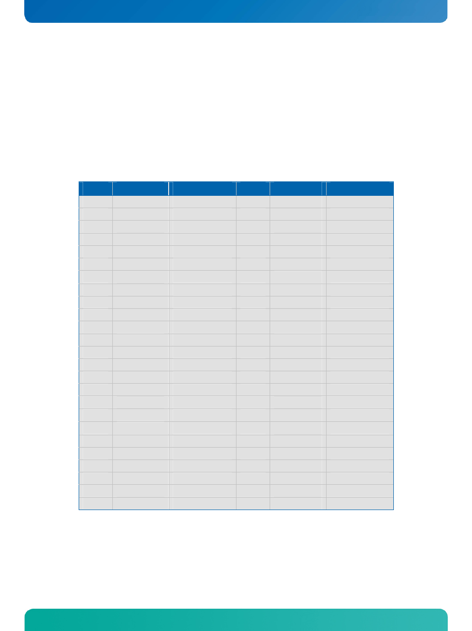
13.2.1 Connector
The CF card interface is available through the standard CF connector X21 (50 pins).
Pin
Signal Name
Function
Pin
Signal Name
Function
1
GND
Ground
2
D3
Data 3
3
D4
Data 4
4
D5
Data 5
5
D6
Data 6
6
D7
Data 7
7
/CS1
Chip select 1
8
GND
Ground
9
GND
Ground
10
GND
Ground
11
GND
Ground
12
GND
Ground
13
VCC
1)
Power +5V
14
GND
Ground
15
GND
Ground
16
GND
Ground
17
GND
Ground
18
SA2
Address 2
19
SA1
Address 1
20
SA0
Address 0
21
D0
Data 0
22
D1
Data 1
23
D2
Data 2
24
N.C.
Not connected
25
GND
Ground
26
GND
Ground
27
D11
Data 11
28
D12
Data 12
29
D13
Data 13
30
D14
Data 14
31
D15
Data 15
32
/CS3
Chip select 3
33
GND
Ground
34
/IOR
I/O read
35
/IOW
I/O write
36
VCC
1)
Power +5V
37
IRQ
Interrupt
38
VCC
1)
Power +5V
39
GND
Ground
40
N.C.
Not connected
41
/RESET
Reset
42
IOCHRDY
I/O channel ready
43
/DRQ
DMA request
44
/DACK
DMA acknowledge
45
ACT
Drive activity
46
N.C.
Not connected
47
D8
Data 8
48
D9
Data 9
49
D10
Data 10
50
GND
Ground