19 feature connector (feature), Feature connector (feature), Kt690 family – Kontron KT690-mITX (BGA) - dual core User Manual
Page 57
KT690 Family
KTD-00738-J
Public User Manual
Date 2012-06-01
Page
57
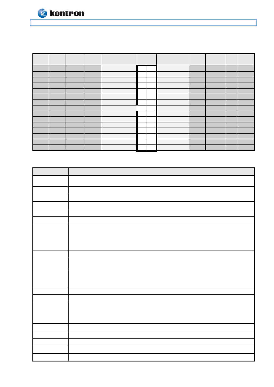
Feature Connector (FEATURE)
4.19
Note
Pull
U/D
Ioh/Iol
Type
Signal
PIN
Signal
Type
Ioh/Iol
Pull
U/D
Note
2
2M/
-
I
INTRUDER#
1
2
GND
PWR
-
-
4
I
EXT_ISAIRQ#
3
4
EXT_SMI#
I
4
PWR_OK
5
6
SB5V
PWR
-
-
-
-
PWR
SB3V3
7
8
EXT_BAT
PWR
-
-
-
-
PWR
+5V
9
10
GND
PWR
-
-
1
4K7/
/12mA
IOT
GPIO0
11 12
GPIO1
IOT
/12mA 2K7/
1
1
4K7/
/12mA
IOT
GPIO2
13 14
GPIO3
IOT
/12mA 2K7/
1
1
4K7/
/12mA
IOT
GPIO4
15 16
GPIO5
IOT
/12mA 2K7/
3
3
4K7/
/12mA
IOT
GPIO6
17 18
GPIO7
IOT
/12mA 2K7/
3
-
-
PWR
GND
19 20
FAN3OUT
FAN3IN
21 22
+12V
PWR
-
-
TEMP3IN
23 24
VREF
-
-
PWR
GND
25 26
IRRX
IRTX
27 28
GND
PWR
-
-
1
2K7/
SMBC
29 30
SMBD
2K7/
1
Note 1: Pull-up to +3V3Dual (+3V3 or SB3V3). Note 2: Pull-up to RTC-Voltage. Note 3: Pull-up to +3V3.
Note 4: NOT supported.
Signal
Description
INTRUDER#
INTRUDER, may be used to detect if the system case has been opened. This signal’s
status is readable, so it may be used like a GPI when the Intruder switch is not needed.
EXT_ISAIRQ#
EXTernal ISA IRQ, (active low input) can activate standard AT-Bus IRQ-interrupt.
EXT_SMI#
External SMI, (active low input) signal can activate SMI interrupt.
PWR_OK
PoWeR OK, signal is high if no power failures is detected.
SB5V
StandBy +5V supply.
SB3V3
Max. load is 0.75A (1.5A < 1 sec.)
EXT_BAT
(EXTernal BATtery) the + terminal of an external primary cell battery can be connected
to this pin. The – terminal of the battery shall be connected to GND (etc. pin 10). The
external battery is protected against charging and can be used with or without the on
board battery installed. The external battery voltage shall be in the range: 2.5 - 4.0 V DC.
Current draw is 3µA when PSU is disconnected.
+5V
Max. load is 0.75A (1.5A < 1 sec.)
GPIO0..7
General Purpose Input/Output. The GPIO’s may be controlled or monitored through the
use of the KT-API-V2 (Application Programming Interface).
FAN3OUT
FAN 3 speed control OUTput. This analogue voltage output signal can be set to output
voltages from 0 – 3V3 to control the Fan’s speed.. For more information please look into
the datasheet for the Winbond I/O controller W83627.
FAN3IN
FAN3 Input. 0V to +3V3 amplitude Fan 3 tachometer input.
+12V
Max. load is 0.75A (1.5A < 1 sec.)
TEMP3IN
Temperature sensor 3 input. (Recommended: Transistor 2N3904, having emitter
connected to GND (pin 25), collector and basis shorted and connected to pin23 (Temp3-
In). Further a resistor 30K/1% shall be connected between pin 23 and pin 24 (Vref).
(Precision +/- 3ºC)
VREF
Voltage REFerence, reference voltage to be used with TEMP3IN input.
IRRX
IR Receive input (IrDA 1.0, SIR up to 1.152K bps)
IRTX
IR Transmit output (IrDA 1.0, SIR up to 1.152K bps)
SMBC
SMBus Clock signal
SMBD
SMBus Data signal