9 printer port connector (printer), Printer port connector (printer), Kt690 family – Kontron KT690-mITX (BGA) - dual core User Manual
Page 45: Printer port connector (printer). 4.9
KT690 Family
KTD-00738-J
Public User Manual
Date 2012-06-01
Page
45
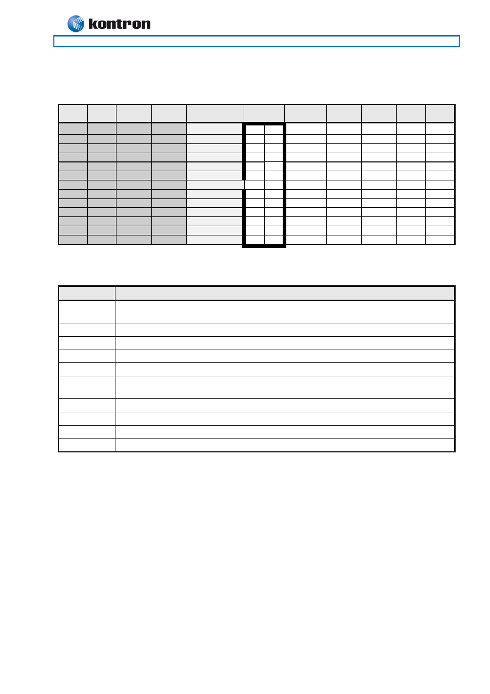
Printer Port Connector (PRINTER).
4.9
The signal definition in standard printer port mode is as follows:
Note
Pull
U/D
Ioh/Iol
Type
Signal
PIN
Signal
Type
Ioh/Iol
Pull
U/D
Note
2K2
(24)/24
OC(O)
STB#
1
2
AFD#
OC(O)
(24)/24
2K2
2K2
24/24
IO
PD0
3
4
ERR#
I
-
2K2
2K2
24/24
IO
PD1
5
6
INIT#
OC(O)
(24)/24
2K2
2K2
24/24
IO
PD2
7
8
SLIN#
OC(O)
(24)/24
2K2
2K2
24/24
IO
PD3
9
10
GND
PWR
-
-
2K2
24/24
IO
PD4
11
12
GND
PWR
-
-
2K2
24/24
IO
PD5
13
14
GND
PWR
-
-
2K2
24/24
IO
PD6
15
16
GND
PWR
-
-
2K2
24/24
IO
PD7
17
18
GND
PWR
-
-
2K2
-
I
ACK#
19
20
GND
PWR
-
-
2K2
-
I
BUSY
21
22
GND
PWR
-
-
2K2
-
I
PE
23
24
GND
PWR
-
-
2K2
-
I
SLCT
25
26
GND
PWR
-
-
The interpretation of the signals in standard Centronics mode (SPP) with a printer attached is as follows:
Signal
Description
PD7..0
Parallel data bus from PC board to printer. The data lines are able to operate in PS/2
compatible bi-directional mode.
SLIN#
Signal to select the printer sent from CPU board to printer.
SLCT
Signal from printer to indicate that the printer is selected.
STB#
This signal indicates to the printer that data at PD7..0 are valid.
BUSY
Signal from printer indicating that the printer cannot accept further data.
ACK#
Signal from printer indicating that the printer has received the data and is ready to accept
further data.
INIT#
This active low output initializes (resets) the printer.
AFD#
This active low output causes the printer to add a line feed after each line printed.
ERR#
Signal from printer indicating that an error has been detected.
PE#
Signal from printer indicating that the printer is out of paper.
The printer port additionally supports operation in the EPP and ECP mode as defined in [3].