Elecraft KRC2 Manual User Manual
Page 9
9
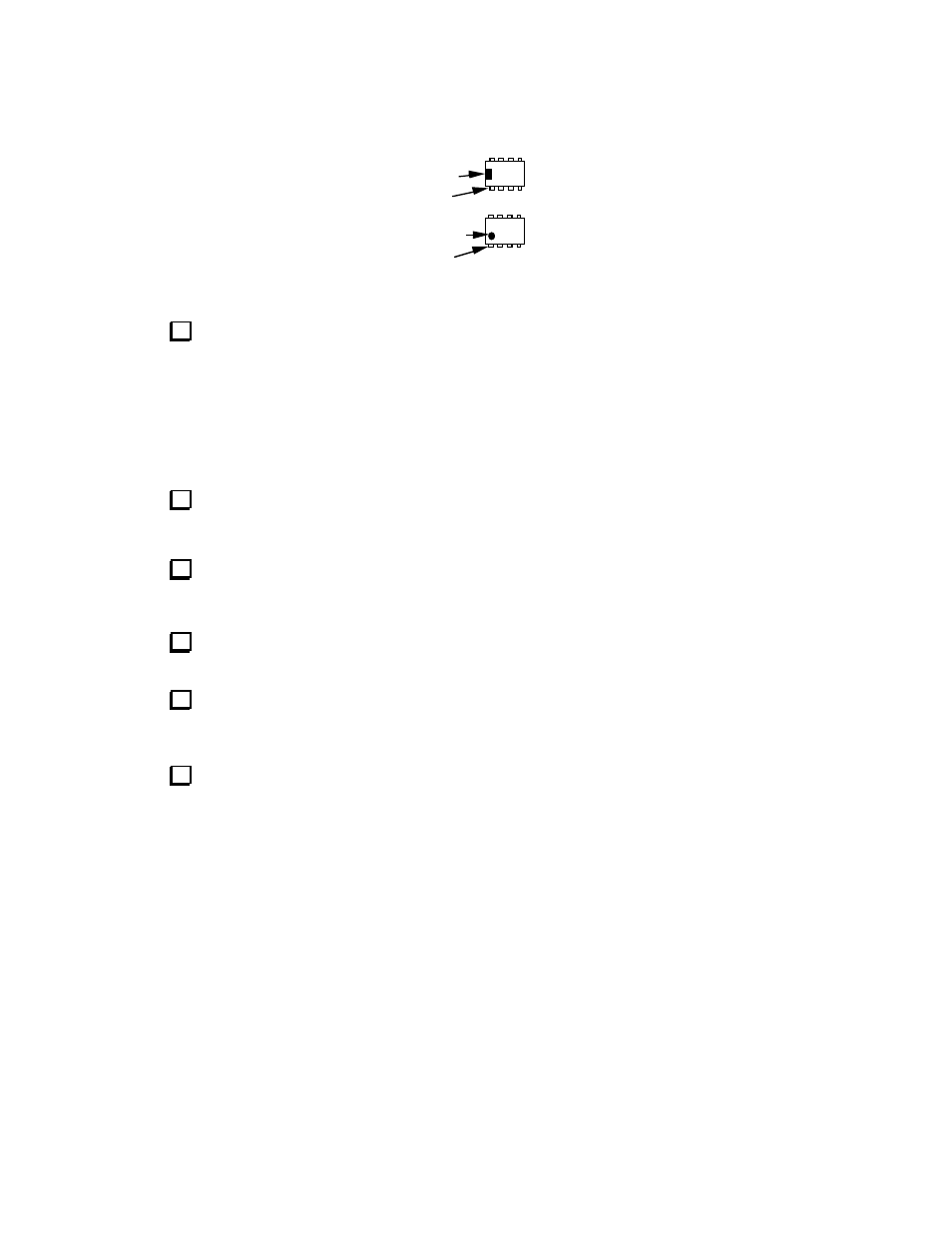
Note: The pin 1 end of ICs can be identified by a notch or dimple as shown in Figure 1. This end
must be oriented toward the notched end of the component outline.
Pin 1
Notch
Pin 1
Dimple
Figure 1
Install the following ICs on the top side of the board. Orient the notched or dimpled end
toward the notched end of their PCB outline (pin 1 end, to the left). Double-check the orientation
before soldering. Be sure to flush-trim the leads of each IC after soldering so as not to interfere
with cables on the bottom side of the board.
__U4
UCN5891A
__U5
UCN5891A
__U6
TPIC6595
__U7
TPIC6595
Install the rectangular Green LED at DS1 on the top side of the board. Spacing the LED
about 1/8” (3 mm) above the board will nicely align the top of the LED with the case top. The dot
marked on the PCB next to DS1 indicates the placement for the longest lead of the LED.
Visual Inspection: Using a magnifying glass, examine the entire board for unsoldered pins,
solder bridges, broken leads, or backward diodes or ICs. Reheat any suspect joints This simple
check could save you hours of troubleshooting later.
The following components will be installed on the bottom side of the circuit board. Turn over
the circuit board to install the components.
Install 1N4007 diodes at D2 and D3 on the bottom side of the PCB. Make sure the cathode
(banded end) of the diode matches the silk-screened outline on the PCB.
__D2,
__D3
Install a 4.7k, 1/8 watt (yel-vio-red) resistor at D1 on the bottom side of the PCB. The
resistor replaces a small diode that was previously used in this position.