Elecraft KRC2 Manual User Manual
Page 26
26
Using the KRC2 with non-Elecraft Radios
The KRC2 is designed to accept band information from radios other than the K2. As discussed in
KRC2 Jumper Configuration, setting jumpers W1-3 for Kenwood mode operations allows the
KRC2 to interface with those radios in a manner similar to the K2. Other radios that do not use
this command set may not be interfaced using this mode.
To use the KRC2 with an ICOM transceiver that has analog (stepped voltage) band output, you
should set the W1-3 jumpers for Analog Mode using the desired input (8R/AN1 or ALC/AN3),
and connect the transceiver’s analog output to the appropriate input pin on J1 or J2. Be sure to
remove W19 or W20 as appropriate. Power the KRC2 using an external 12-volt supply connected
to the KRC2’s DC barrel jack. The KRC2 should now set its band outputs according to the voltage
presented by the radio.
The three analog inputs have slightly different characteristics you should consider when choosing
which to use. The 8R/AN1 and ALC/AN3 inputs have voltage divider networks on their inputs
that divide the input by 2. Thus their input range is from 0 to 10 volts. The VRDET/AN2 input has
no divider network, giving it a voltage range of 0 to 5 volts. Each input voltage is filtered through
a band selection table that determines the selected band. There are three tables, one for each input.
The factory-configured tables are set up for Icom radios with voltage range of 0 to 8 volts for the
wide-range inputs, with the third table set for the Yaesu FT-817 transceiver’s analog output. These
tables are user-configurable using the KRC2 Configuration tool
To use the KRC2 with a Yaesu radio or computer parallel port outputs, set jumpers W1-3 as
follows: W1 OUT, W2 IN, W3 OUT as described in Table 2. You may then connect the radio or
computer outputs to the KRC2’s ABCD terminals, with the return ground connected to one of the
terminals labeled ‘G’. Power the KRC2 from an external 12-volt supply connected to the DC
barrel jack. The unit should now switch the driver outputs in accordance to the digital inputs it
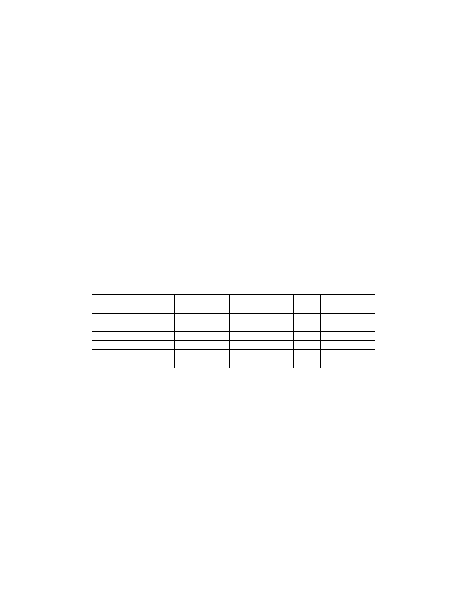
sees. Note that in addition to the standard BCD outputs, the KRC2 recognizes additional band
codes according to Table 5.
Binary coding
Hex
Band
Binary coding
Hex
BAND
0001
01
160m
1000
08
12m
0010
02
80m
1001
09
10m
0011
03
40m
1010
0A
60m
0100
04
30m
1011
0B
unused
0101
05
20m
1100
0C
XVT1
0110
06
17m
1101
0D
XVT2
0111
07
15m
1110
0E
XVT3
Table 6