Elecraft KRC2 Manual User Manual
Page 13
13
Adjacent to J1, on the bottom side of the board, you will find two pads connected by a white
line. Using one of the 1N4007 diode leads previously saved, install a 1/4" (6 mm) tall U-shaped
ground jumper between these two pads, on the bottom side of the board. This jumper can be used
as a ground point for test instruments.
Locate the remaining three pushbutton switches. These will now be installed on the top side
of the board. Insert the switches into their mounting holes at S2, S3 and S4, spreading the legs
slightly so they will properly engage the holes. Press the switch down until it is fully seated on the
bends in its leads. There will be a slight gap between the switch body and PCB. Solder the
switches onto the circuit board from the top side.
__S2,
__S3
__S4
Locate the four pushbutton key caps. Making sure the key caps are oriented from end-to-end
across the board, press the key caps onto the pushbutton switch stems until they lock into place.
i
Before handling U1, touch an unpainted, grounded metal surface.
i
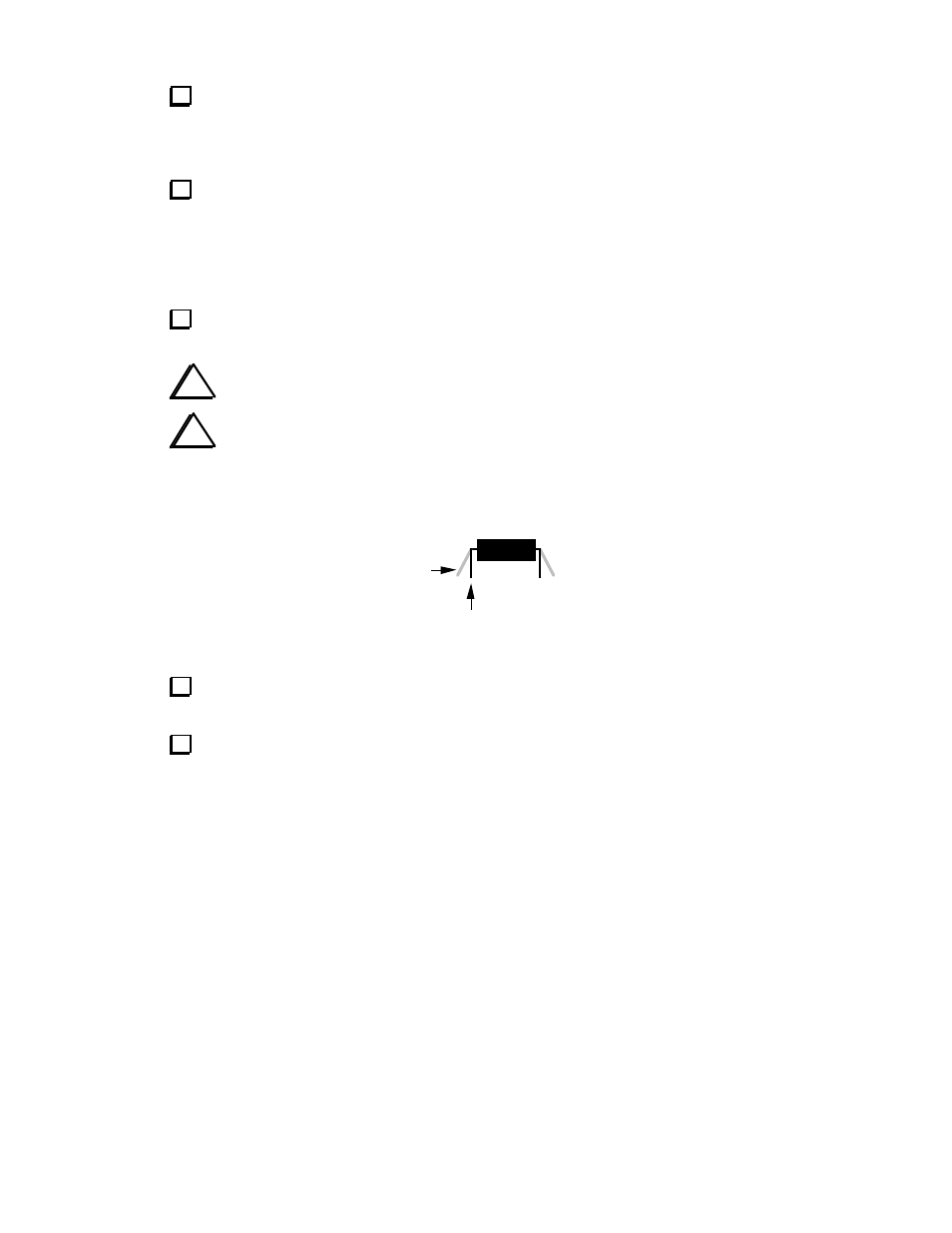
When you install the IC in the following step, always straighten the leads of the IC first as
shown in Figure 4. The two rows of pins must be straight and parallel to each other to establish the
proper pin spacing for insertion into the PC board or socket. To straighten the pins, rest one entire
row of pins against a hard, flat surface. Press down gently on the other row of pins and rock the IC
forward to bend the pins into position as shown below.
Straight
Flared
Figure 4
Carefully straighten the pins on the microcontroller, U1 (PIC16F877A). The two rows of pins
must be parallel to each other, with no pins bent.
Press the microcontroller into its socket, orienting the notched or dimpled end of the IC with
the notched end of its component outline. The labeling on the microcontroller should read from
left to right.
This completes assembly of the KRC2 circuit board. There are two remaining parts locations, R5
and SP1, which are used with the accessibility speaker option. All other component locations
should now be filled.