Elecraft KRC2 Manual User Manual
Page 23
23
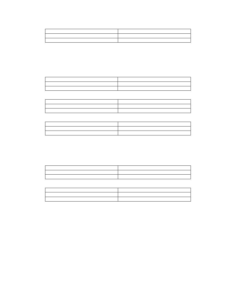
• K2 serial port used for band, data and control communications. Stand-alone (no PC):
The KRC2ACC may use this setup for communications with the K2.
Installed
Removed
W3, W6
W1, W2, W7, W8
W9 -W19, W21-W23
W20
Elecraft K3. The preferred setup for the K3 uses the AuxBus for band communications. This
mode uses the K3’s AuxBus for band communications.. Connect J1/J2 pin 6 to pin 2 of the K3’s
AuxIO connector. J1/J2 pin 1 (Ch Gnd) should be connected to K3 Aux IO pin 5. The KRC2 may
also be connected to the K3’s serial port to determine bands. In this configuration control and data
communications will be functional, however not all K3 commands or data may be recognized by
the KRC2.
• AuxBus. Control and data transfers are not available.
Installed
Removed
W1, W2, W3, W6, W7, W8
W9 -W23
• Serial port, PC Logging in use, data rate set to 19200 bps:
Installed
Removed
W3, W8
W1, W2, W6, W7
W9, W10, W21-W23
W11-W20
• Serial port, (no PC), data rate set to 19200 bps:
Installed
Removed
W3, W6, W8
W1, W2, W7
W9, W10, W21-W23
W11-W20
Kenwood. This mode uses Kenwood’s serial port for control and data communications. The data
rate may be set using the W7 and W8 jumpers as required. See Table 3 for this information. Some
Kenwood radios require the use of RTS/CTS handshaking in order to enable communications. If
this is required with your radio, connect a jumper wire from W14 to W17. The wire should be
connected to the jumper pins nearest the DB-9 connectors.
• PC Log program in use, data rate of 19200 bps
Installed
Removed
W3, W6, W8
W1,W2, W7
W9, W10, W21-W23
W11-W20
• Stand-alone (no PC) operation, data rate of 19200 bps
Installed
Removed
W3, W6, W8
W1, W2, W7
W9, W10, W21-W23
W11-W20