Elecraft KRC2 Manual User Manual
Page 25
25
KRC2 Power Connections
The KRC2 may be powered from one of several sources. The
microcontroller and logic are powered either from the K2 through the
DB-9 connector, or from the +12V DC barrel jack. The voltage
applied at the DC barrel jack must not exceed 15 volts.
Power for the Source drivers can come either from the DC barrel jack
or the J5 terminal connector. Voltage applied to the J5 ‘V’ terminal
must not exceed +50 volts. Maximum current drain for either source is
1 amp.
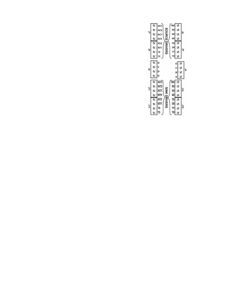
Connecting the KRC2’s Drivers
There are 36 driver output terminals. The terminals are accessible by
removing two access screws on the bottom case. Sixteen of the drivers
will source current, and another sixteen will sink current. The
remaining four drivers, labeled A, B, C and D, are TTL-compatible
inputs or outputs depending on the operating mode. In normal KRC2
or analog modes, the terminals are outputs. In digital parallel input
mode, they become inputs, and receive the BCD-encoded band data.
An additional four terminals are provided for connecting the KRC2 to
ground returns, and to provide a supply voltage for the source drivers
as described in the KRC2 Power Connections section. Figure 8
illustrates the connections. A bar over the terminal label indicates the
output is a sink driver. Sink driver terminals are located near the front
of the box. Source drivers are located toward the rear of the box.
Like-drivers may be wire-ORed (connected together) in order to allow a relay to be selected on
more than one band. For example, the control line from a tri-band beam would connect to
terminals 20, 15 and 10 for source drivers, or /20, /15 and /10 for sink drivers.
IN NO CASE SHOULD THE SOURCE AND SINK TERMINALS BE CONNECTED
TOGETHER IN ANY WAY!
Connecting other Elecraft Peripherals
Additional Elecraft peripherals, such as a KAT-100 or XV-Series transverter, may be connected to
the KRC2’s PC port in a “daisy-chain” fashion in order to operate with the K2. Simply plug the
DB-9 connector from the peripheral into the KRC2’s PC port, and use the peripheral as if it were
directly connected to the K2. Be sure to follow the rules outlined in the jumper discussion and
insert all jumpers in the W9-W23 block with the exception of W20 when using this configuration.
KRC2 PC Connections
A personal computer’s RS-232 serial port may be connected to the KRC2’s PC port using the PC
connector. Normally the K2 does not automatically report its settings to the KRC2. If you have an
alternate KRC2 configuration that needs for the K2 to report its settings, install jumper W6 to
enable the K2’s auto-report mode.
Figure 8