Elecraft KRC2 Manual User Manual
Page 12
12
Install J1, a female PC-mount DB9 connector on the bottom side of the PCB. This position is
approximately in the center at the end of the PCB. The connector will “snap” into the board as its
mounting tabs “grab” the board. Be sure you have installed the FEMALE connector (with sockets)
before soldering the connector pins onto the board.
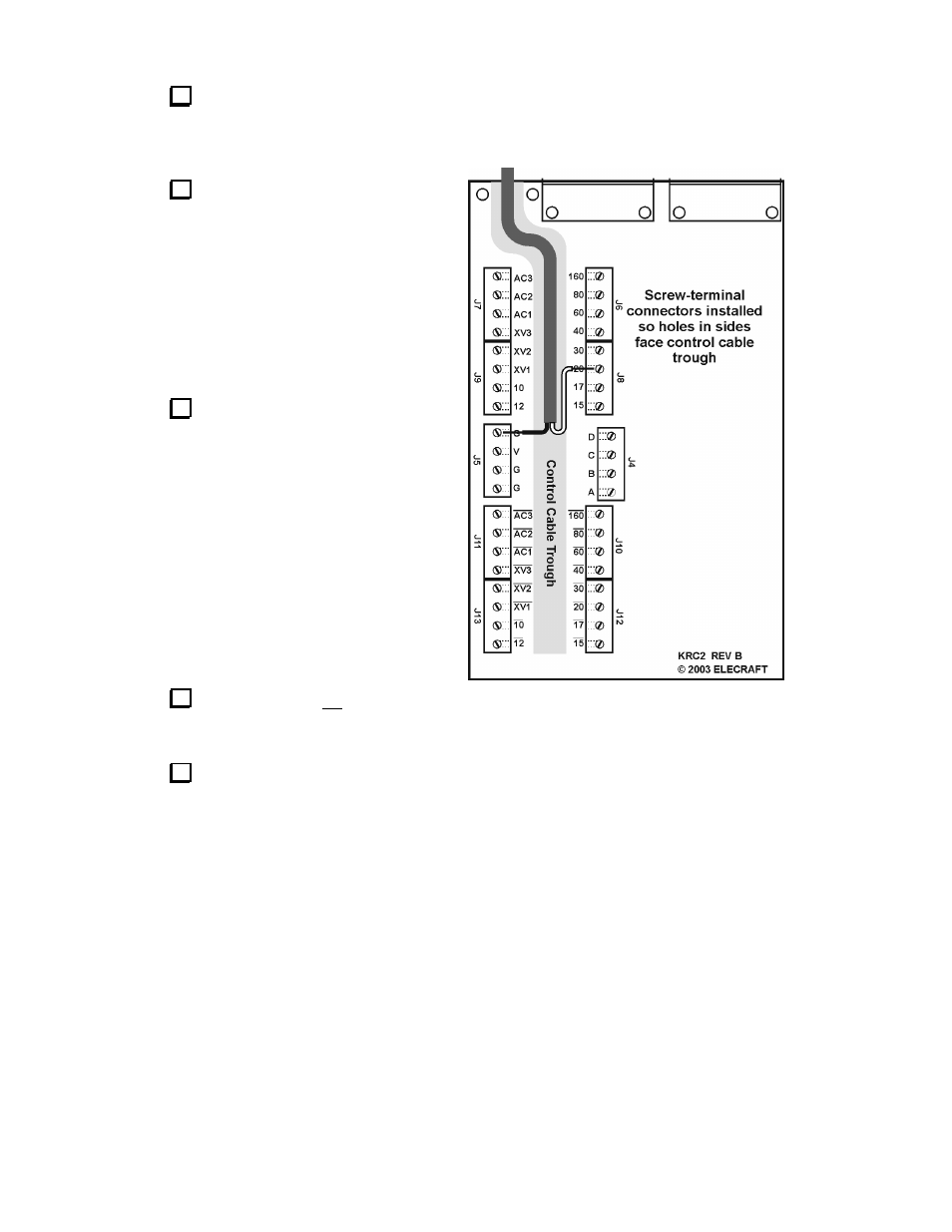
Refer to Figure 3, and install screw
terminal connectors at J4 and J5 on the
bottom side of the PCB. The opening
between the connectors forms a “trough” for
control cables to external devices. The
terminals must be mounted so their side
openings face this trough. Make sure the feet
of the terminals are firmly seated against the
board, leaving a very slight gap between the
body of the terminal and the PCB.
__J4,
__J5
Connect two terminals together end-to
end by sliding the tab of one connector into
the slot of another. This forms a single 8-pin
connector. Form three other eight-pin
terminals following the same procedure, then
install the screw terminals at the locations
indicated in Figure 3 on the bottom side of
the PCB. Make sure the terminals are
mounted so their side openings face the
trough. Also make sure the feet of the
terminals are firmly seated against the board,
leaving a very slight gap between the body of
the terminal and the PCB.
__J6/J8
__J7/J9,
__J10/J12,
__J11/J13
Install crystal X1, a
tall , 4.000 MHz
device,
on the bottom side of the PCB. Make sure it is flat against the board before soldering. Use
a minimum of solder to avoid the solder wicking through to the other side, causing a short.
Locate the ground pad near X1. Insert a discarded component lead through this pad, then fold
it over the top of X1. Solder this lead at the ground pad, then solder it to the crystal can. Avoid
overheating the crystal.
Figure 3